Composite Wing Panels and Fabrication Method

a composite structure and wing panel technology, applied in the field of composite structure fabrication, can solve the problems of reducing throughput, requiring a substantial amount of factory floor space, and not being fully efficient, so as to achieve the effect of reducing throughput, increasing flow times, and increasing production costs

Pending Publication Date: 2022-05-19
THE BOEING CO
View PDF0 Cites 0 Cited by
  • Summary
  • Abstract
  • Description
  • Claims
  • Application Information

AI Technical Summary

Problems solved by technology

The production of large composite structures such as aircraft wings spanning up to 100 feet or more requires a substantial amount of factory floor space.
Although the wing panel production method described is reliable, it is less than fully efficient.
The need to move wing panel components between work cells and delays experienced in individual cells adds to flow times and reduces throughput.

Method used


Image

  • Composite Wing Panels and Fabrication Method
  • Composite Wing Panels and Fabrication Method
  • Composite Wing Panels and Fabrication Method

Examples


Embodiment Construction

[0082]The figures and the following description provide specific illustrative examples of the disclosure. It will thus be appreciated that those skilled in the art will be able to devise various arrangements that, although not explicitly described or shown herein, embody the principles of the disclosure and are included within the scope of the disclosure. Furthermore, any examples described herein are intended to aid in understanding the principles of the disclosure, and are to be construed as being without limitation to such specifically recited examples and conditions. As a result, the disclosure is not limited to the specific example or examples described below, but by the claims and their equivalents.

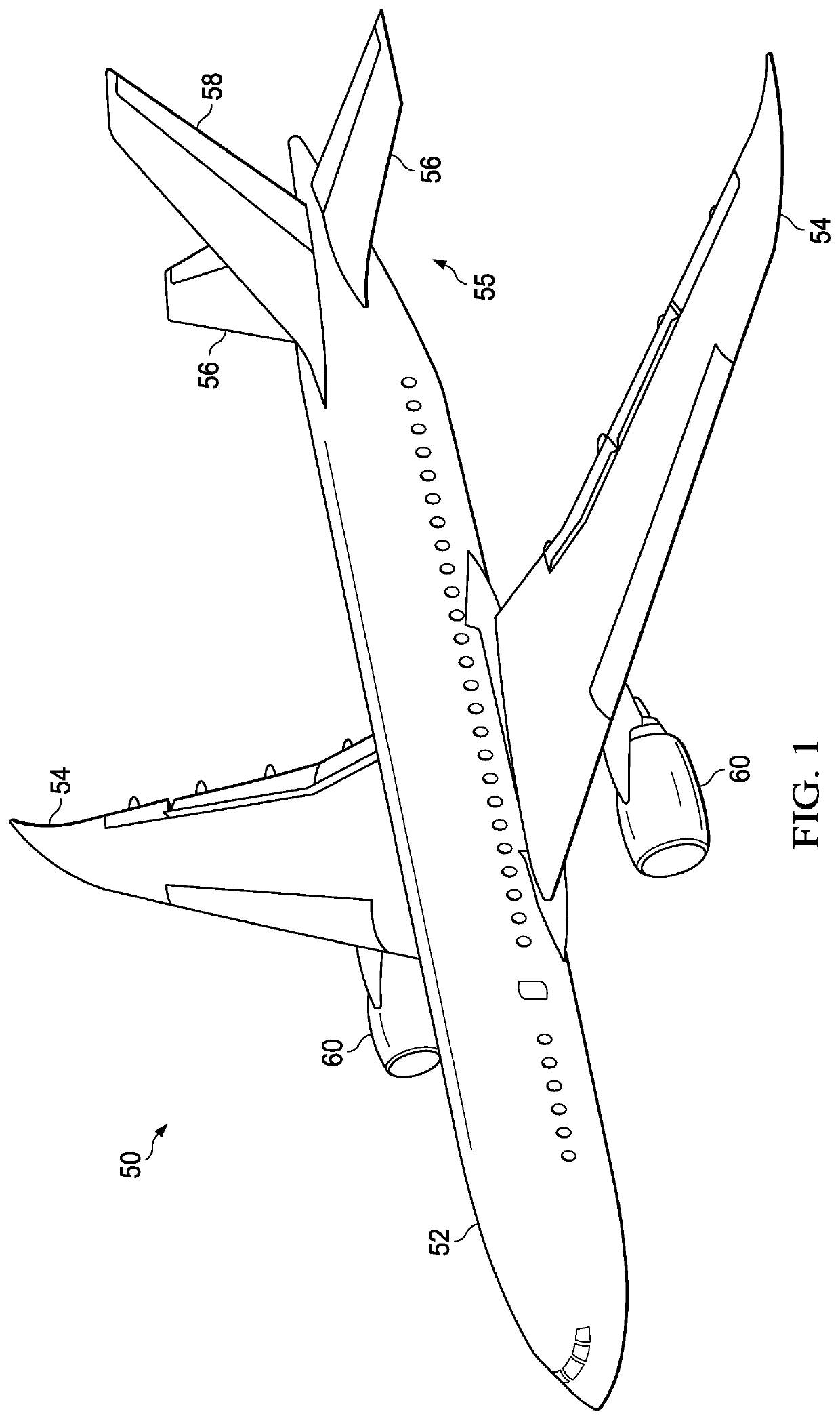
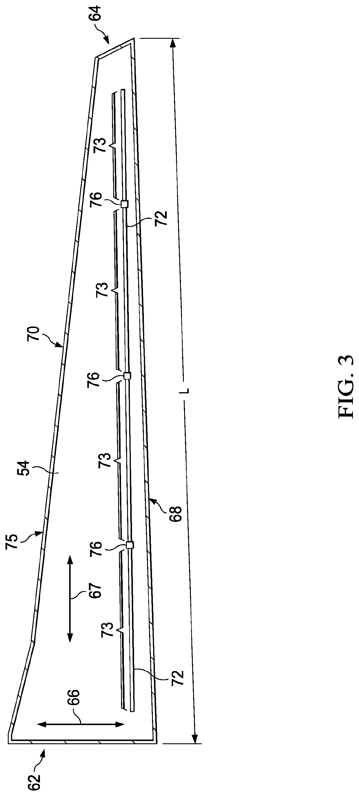
[0083]The wing panels described herein comprise one or more composite parts. Composite parts, such as Carbon Fiber Reinforced Polymer (CFRP) parts, are initially laid-up in multiple layers that together are referred to as a preform. Individual fibers within each layer of the preform...


PUM

PropertyMeasurementUnit
movementaaaaaaaaaa
lengthaaaaaaaaaa
volumeaaaaaaaaaa

Abstract

Wing panels having composite wing skins and stringers are produced on a moving production line. The wing panels are formed on mandrels that move through workstations along the production line where laminators layup the wing skins and pick-and-place machines place stringers on the wing skins that are supplied by stringer feeder lines.

Description

CROSS-REFERENCE TO RELATED APPLICATION[0001]This application claims the benefit of U.S. Provisional Patent Application Ser. No. 63 / 115,167, filed Nov. 18, 2020, and entitled “Composite Wing Panels and Fabrication Method;” which is incorporated herein by reference in its entirety.BACKGROUND INFORMATION1. Field[0002]The present disclosure generally relates to the fabrication of composite structures, and deals more particularly with composite wing panels for aircraft as well as a method of fabricating such panels.2. Background[0003]The production of large composite structures such as aircraft wings spanning up to 100 feet or more requires a substantial amount of factory floor space. In a volume production environment, such structures are often fabricated and assembled in individual work cells on a factory floor, each dedicated to a particular task or process. For example, in the case of wing panels, a layup mandrel may be cleaned and prepared for use in a work cell, and then transferre...

Claims


Application Information

Patent Timeline
Patent Type & Authority Applications(United States)
IPC IPC(8): B64F5/10B64C3/26B64C3/18B29C70/30
CPCB64F5/10B64C3/26B29L2031/3085B29C70/30B64C3/182B64C3/00B29C70/34B29C70/54Y02T50/40Y02P70/50
Inventor SMITH, DANIEL R.JONES, DARRELL DARWIN
Owner THE BOEING CO
Why Eureka
Try Eureka