
Light field-based beam correction systems and methods

a beam correction and field-based technology, applied in the field of light beam correction, can solve the problems of lossy wavefront, additional error, lossy wavefront,

Pending Publication Date: 2022-06-02
UNIV OF MARYLAND
View PDF4 Cites 3 Cited by
  • Summary
  • Abstract
  • Description
  • Claims
  • Application Information

AI Technical Summary

Benefits of technology

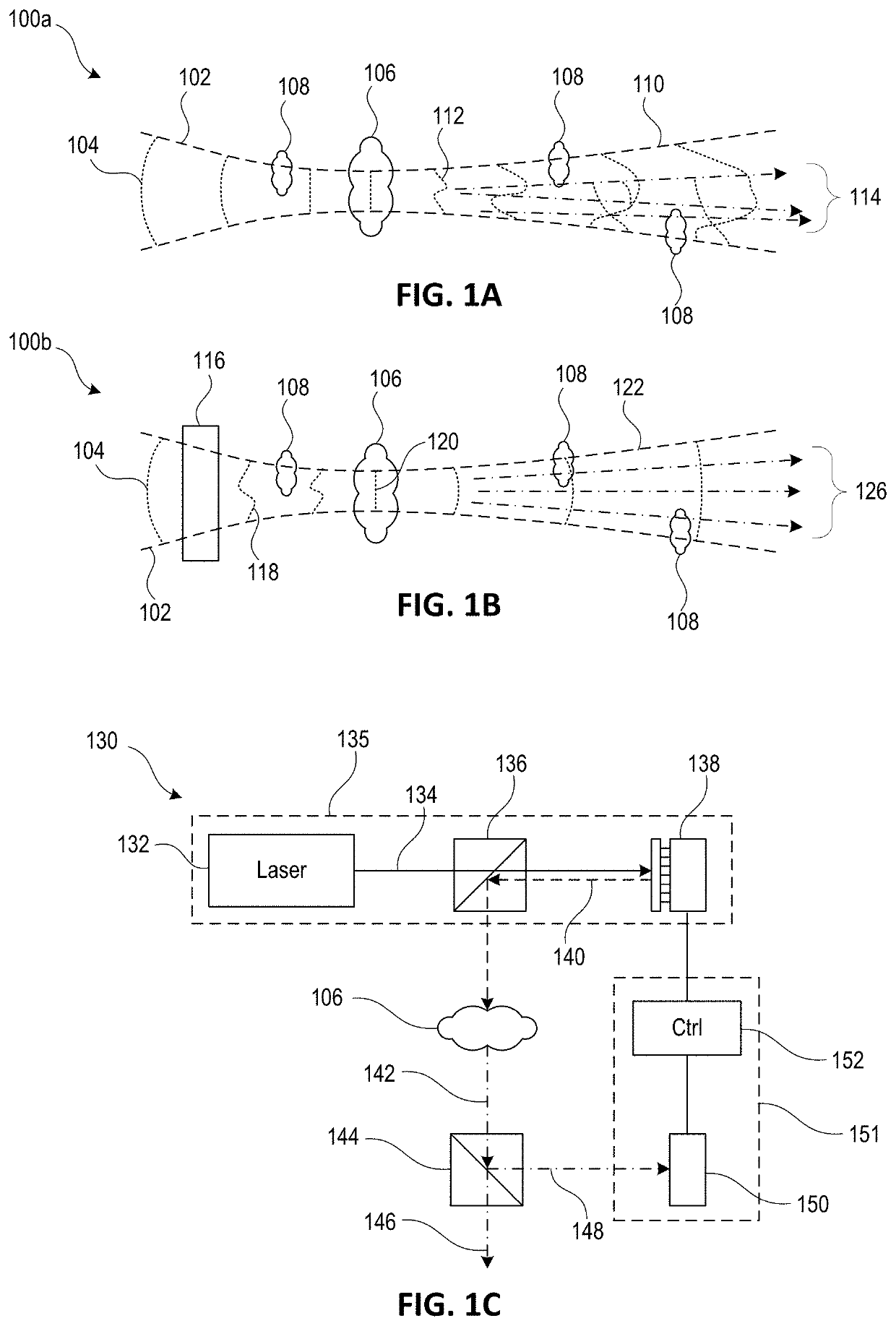
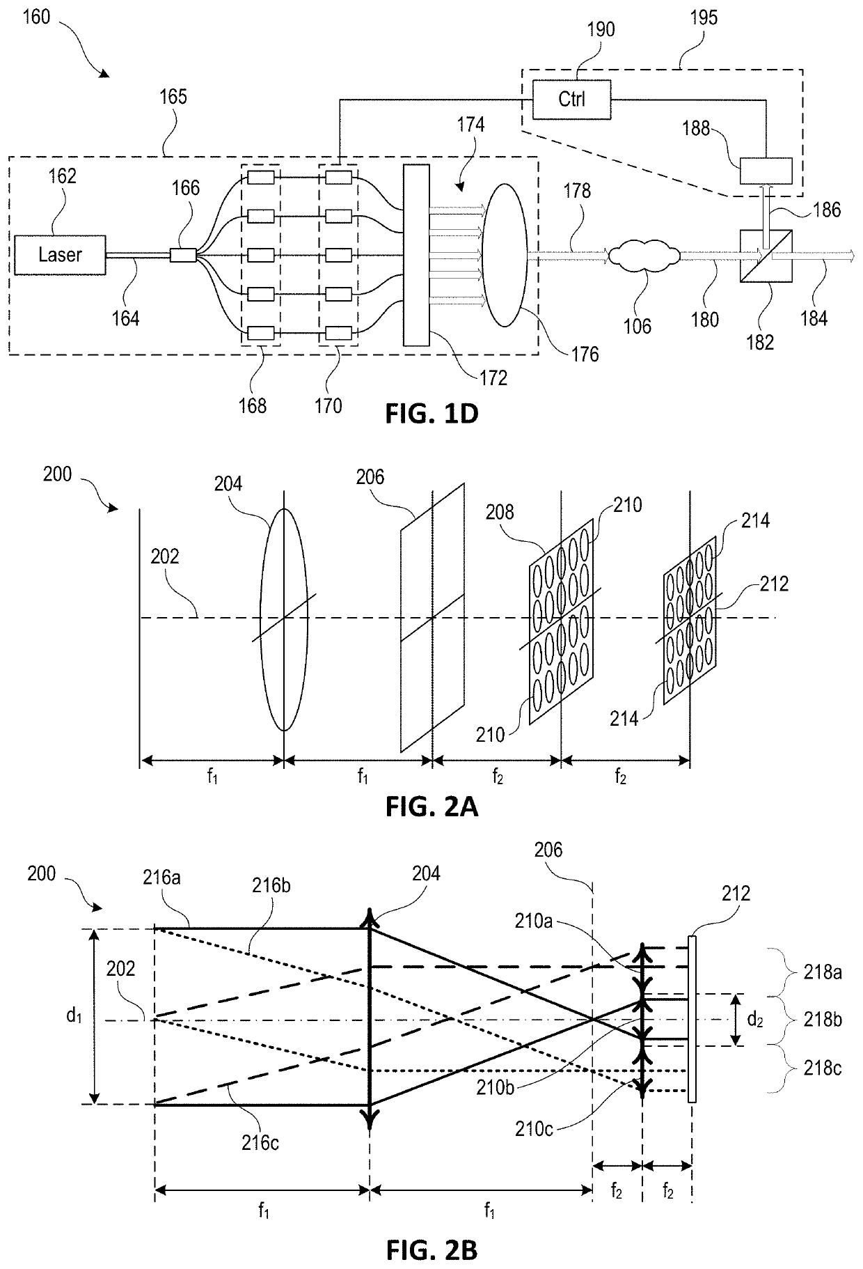
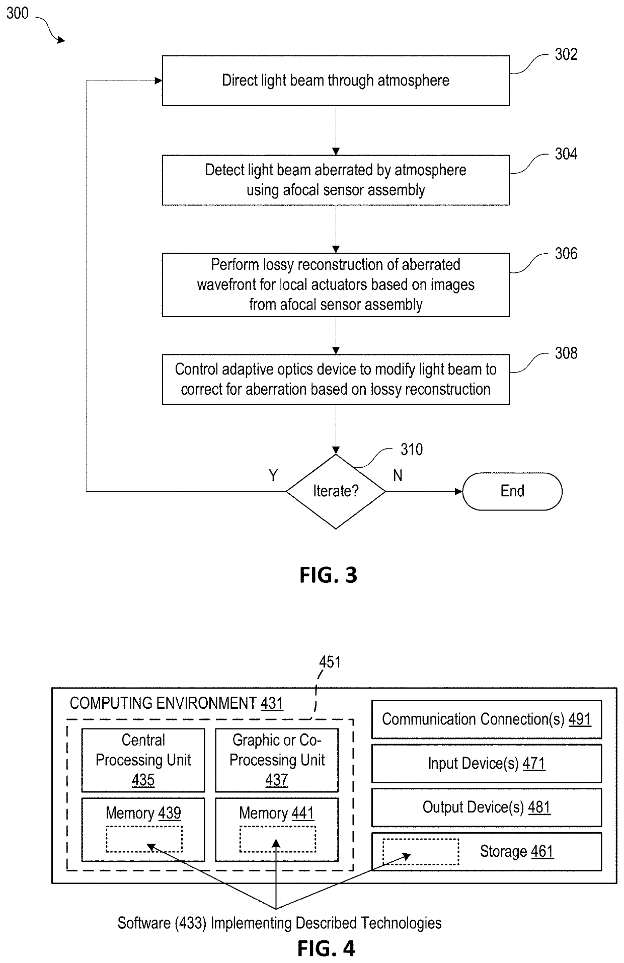
The patent text describes a system and method for analyzing and correcting a sampled light beam using an afocal sensor assembly and an adaptive optics (AO) device. The system can correct for aberrations in the light beam caused by turbulence in the atmosphere, providing a more accurate analysis of the light beam. The AO device can include a deformable mirror, a digital micromirror array, or a pyramid wavefront sensor, and can be controlled based on information from the sensor to correct the light beam in real-time. The system can be used in applications such as ground-to-ground optical systems, free-space laser communications, and remote sensing. The method can involve directing a light beam through atmospheric turbulence and detecting it using a plenoptic sensor module. The plenoptic sensor module can include an objective lens assembly, a microlens array, and a photodetector. The reconstructed wavefront can be used to control the AO device to correct for aberrations in the light beam.

Problems solved by technology

In general, light beam detection can be considered lossy in revealing the wavefront if (a) the data are subsampled (e.g., information is lost) and / or (b) the reconstruction has multiple interpretations (e.g., contains ambiguity).
Additional error can occur when formulating the lossy wavefront reconstruction to the AO device (e.g., a deformable mirror, a digital micromirror array device, a spatial light modulator, or phase modulators of a fiber laser phased array) controls, for example, due to limitations of the influence function (e.g., cross-coupling between actuators due to membrane stiffness of a deformable mirror) and / or stroke ranges.
Lossy sensing can thus lead to errors between actual and reconstructed values at these nodes, which facilitates direct evaluations.
Otherwise, the situation cannot be easily resolved, and phase reconstruction is path dependent.
Unless continuous phase structure is guaranteed, where minimum mean square error reconstruction can be safely applied, a branch in any existing loop in the measured sij set can be removed for reconstruction, such that the resulting reconstruction process will be lossy.

Method used


Image

  • Light field-based beam correction systems and methods
  • Light field-based beam correction systems and methods
  • Light field-based beam correction systems and methods

Examples


Embodiment Construction

General Considerations

[0031]For purposes of this description, certain aspects, advantages, and novel features of the embodiments of this disclosure are described herein. The disclosed methods and systems should not be construed as being limiting in any way. Instead, the present disclosure is directed toward all novel and nonobvious features and aspects of the various disclosed embodiments, alone and in various combinations and sub-combinations with one another. The methods and systems are not limited to any specific aspect or feature or combination thereof, nor do the disclosed embodiments require that any one or more specific advantages be present, or problems be solved. The technologies from any embodiment or example can be combined with the technologies described in any one or more of the other embodiments or examples. In view of the many possible embodiments to which the principles of the disclosed technology may be applied, it should be recognized that the illustrated embodimen...


PUM


Abstract

An afocal sensor assembly detects a light beam with an aberrated wavefront. The afocal sensor assembly is configured to provide sorted four-dimensional (4D) light field information regarding the light beam, for example, via one or more plenoptic images. Based on the 4D light field information, a lossy reconstruction of an aberrated wavefront for one or more actuators of an adaptive optics (AO) device is performed. The AO device can be controlled based on the lossy reconstruction to correct the wavefront of the light beam. In some embodiments, the aberrated wavefront is due to passage of the light beam through atmospheric turbulence, and the lossy reconstruction and correction using the AO device is performed in less than 1.0 ms. The lossy reconstruction of the aberrated wavefront can have a phase accuracy in a range of λ / 2 to λ / 30.

Description

CROSS-REFERENCE TO RELATED APPLICATION[0001]The present application claims the benefit of U.S. Provisional Application No. 63 / 120,655, filed Dec. 2, 2020, entitled “Light Field-Based Beam Correction System and Method of Using the Same,” which is incorporated by reference herein in its entirety.STATEMENT REGARDING FEDERALLY SPONSORED RESEARCH[0002]This invention was made with government support under N000141211029, N000141612944, and N000141812008 awarded by the Office of Naval Research (ONR). The government has certain rights in the invention.FIELD[0003]The present disclosure relates generally to light beam systems, and more particularly, to light beam correction based at least in part on detected light field information.SUMMARY[0004]Embodiments of the disclosed subject matter system can employ an afocal sensor assembly to analyze a sampled light beam by its four-dimensional (4D) light field and can subsequently guide an adaptive optics (AO) device to correct the light beam for aber...

Claims


Application Information

Patent Timeline
Patent Type & Authority Applications(United States)
IPC IPC(8): G02B27/09H04N5/225G02B3/00G06T7/557G02B27/00G06T7/70
CPCG02B27/0916H04N5/22541G02B3/0037G06T2207/10052G02B27/0025G06T7/70G06T7/557G02B3/0056G02B27/0087G02B27/10G02B27/0068H04N23/957
Inventor WU, CHENSHENGKO, JONATHANRZASA, JOHN R.DAVIS, CHRISTOPHER C.PAULSON, DANIEL
Owner UNIV OF MARYLAND
Learn More