Lid body and sealed battery

a technology of sealed batteries and lids, applied in the direction of cell sealing materials, cell components, electrical equipment, etc., can solve the problems of difficult to prevent peeling at the joint surface of sealing materials and terminals, and the battery performance is affected

Pending Publication Date: 2022-06-02
PRIME PLANET ENERGY & SOLUTIONS INC +1
View PDF0 Cites 0 Cited by
  • Summary
  • Abstract
  • Description
  • Claims
  • Application Information

AI Technical Summary

Benefits of technology

[0006]Attempts have been made in recent years to reduce the number of parts used in batteries, for the purpose of cutting manufacturing costs. For instance, an approach has been studied in which a terminal or sealing plate made of a metal is directly joined to a sealing material made up of a resin material, without using a component for joining the terminals by crimping. In the case of direct joining the sealing material and the terminal together, peeling at the joint surface therebetween may occur due to expansion or contraction of the component caused by changes in temperature. When peeling occurs at the joint surface, the sealability of the sealing material drops, which translates into impaired battery performance.
[0011]A sealing material containing an inorganic filler is used in the lid body for a sealed battery disclosed herein. As described above, the inorganic filler is oriented so that the angle formed between the inorganic filler and the surface of the sealing plate is small. An orientation direction of the inorganic filler aligns with the direction of expansion or contraction of the sealing plate, as the sealing plate expands or contracts accompanying changes in the temperature of the usage environment of the sealed battery, and hence also the sealing material readily expands or contracts conforming to the sealing plate. That is, it becomes possible to reduce stress acting on the surface at which the metal member and the sealing material are joined, and to reduce friction acting on the surface at which the metal member and the sealing material are in contact. As a result, peeling at the surface at which the sealing material is joined to the metal member can be made unlikelier, and also the sealability of the sealing material can be suitably maintained. A sealed battery of favorable cold / heat resistance is provided by using a lid body having such a sealing material.
[0013]In such a configuration, the orientation of the inorganic filler can be readily aligned, also at the time of molding of the sealing material for instance by injection molding, and the above-described effect is brought out yet more suitably.
[0015]In such a configuration, the coefficient of linear expansion of the sealing material in the orientation direction does not significantly deviate from those of the sealing plate and of the terminal member. As a result, the sealing material conforms yet more readily to the expansion or contraction of the various members, and sealability can be maintained yet more suitably.
[0019]In a sealed battery having such a configuration, stress acting on a joint surface of the sealing material and the negative electrode terminal member is reduced. Peeling at the joint surface is rendered unlikelier as a result.

Problems solved by technology

When peeling occurs at the joint surface, the sealability of the sealing material drops, which translates into impaired battery performance.
Even if the mechanical strength of the sealing material is improved, it is, however, difficult to prevent peeling at the joint surface of the sealing material and the terminal due to expansion or contraction of the component caused by changes in temperature.

Method used


Image

  • Lid body and sealed battery
  • Lid body and sealed battery
  • Lid body and sealed battery

Examples


example 1 to example 5

[0063]Herein PPS (polyphenylene sulfide) and glass fibers having an average aspect ratio of 2 were prepared to a ratio by weight of the foregoing of PPS:glass fibers=80:20. Then PPS was melted at 330° C., and was mixed with an inorganic filler, to prepare an injection molding material.

[0064]There were prepared a 50 mm×50 mm×3 mm test pieces made of aluminum, and having a φ8 mm through-hole in the center. One of the surfaces of each test piece was subjected to a surface roughening treatment by laser irradiation.

[0065]A mold was prepared, for the surface of the test piece having undergone the surface roughening treatment, such that the through-hole of the test piece was plugged and such that a φ16 mm×3 mm injection molded body could be molded at the center of the test piece. The test piece was then placed in the mold.

[0066]A test molding material at 330° C. was filled in while modifying in various ways the injection rate in the mold.

[0067]Once the test molding material had cooled and ...

example 6

[0068]Test sample example 6 was produced in the same way as in Example 4 but using herein glass fibers having an average aspect ratio of 1.6 as the glass fibers mixed with PPS.

[0069]Measurement of the Average Orientation Angle

[0070]The produced Test sample examples 1 to 6 were subjected to cross-sectional SEM observation, and the respective average orientation angles were measured in accordance with the above-described method. The results are given in Table 1.

TABLE 1Average orientationThermal cyclingTest sampleangleAverage aspect ratioresistanceExample 1 5°2GoodExample 215°2GoodExample 320°2GoodExample 430°2GoodExample 540°2PoorExample 630°1.6Poor

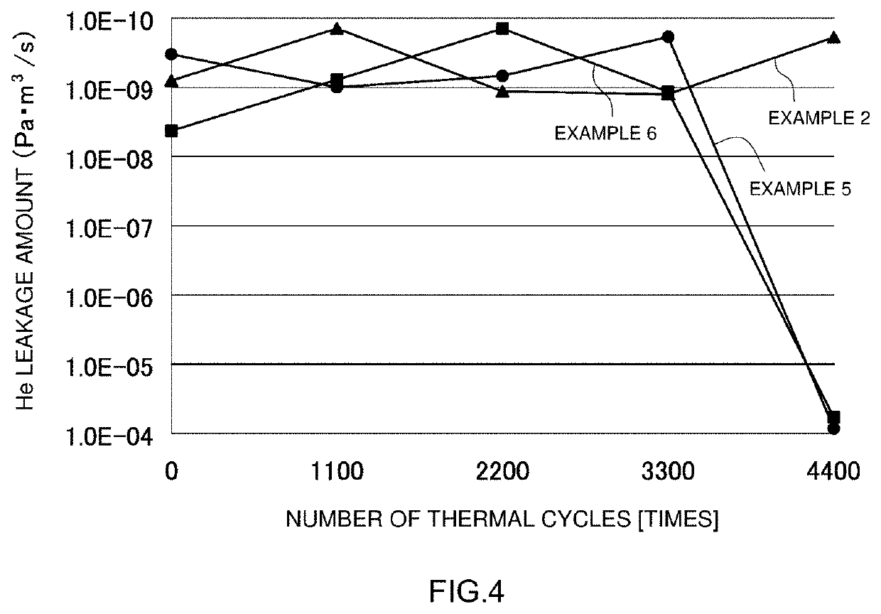
[0071]Thermal Cycling Test

[0072]Thermal cycling from −65° C. to 120° C. was carried out, over 5500 cycles, for Test sample examples 1 to 6.


PUM

PropertyMeasurementUnit
orientation angleaaaaaaaaaa
aspect ratioaaaaaaaaaa
average aspect ratioaaaaaaaaaa

Abstract

A lid body including: a terminal member of at least one electrode; a sealing plate having a mounting hole for attaching the terminal member; and a sealing material containing an inorganic filler. The terminal member is inserted into the mounting hole and is attached to the sealing plate in a state where the sealing material is joined to a peripheral edge portion of the mounting hole. In a microscope observation of a cross section of the sealing material, an average aspect ratio of the inorganic filler is 2 or higher, and with an average orientation angle of the inorganic filler is 30 degrees or smaller, in at least the sealing material formed on an outer surface of the sealing plate.

Description

BACKGROUND OF THE INVENTION1. Field of the Invention[0001]The present disclosure relates to a lid body and to a sealed battery that utilizes the lid body. More specifically, the present disclosure relates to a lid body provided with a sealing material, and to a sealed battery that utilizes the same. The present application claims priority based on Japanese Patent Application No. 2020-198150 filed on Nov. 30, 2020, the entire contents whereof are incorporated in the present specification by reference.2. Description of the Related Art[0002]Nonaqueous electrolyte secondary batteries such as lithium ion secondary batteries have become increasingly important as vehicle-mounted power sources and power sources for personal computers and mobile terminals. In particular, lithium ion secondary batteries, which are lightweight and afford high energy densities, are preferably used as high-output power sources mounted on vehicles.[0003]Secondary batteries of this type are constructed, for instan...

Claims


Application Information

Patent Timeline
Patent Type & Authority Applications(United States)
IPC IPC(8): H01M50/167H01M50/15
CPCH01M50/167H01M50/15H01M50/176H01M50/188H01M50/198H01M50/195H01M50/184H01M10/0525H01M10/0587H01M50/159H01M50/562Y02E60/10
Inventor SATO, YUKIUCHIDA, YOZOASADACHI, HIDEKIEHARA, TSUYOSHITSUCHIYA, SYOICHIASAI, MASATAKAASANO, TSUYOSHIUCHIMURA, MASAHIROTATEYAMA, NOZOMI
Owner PRIME PLANET ENERGY & SOLUTIONS INC
Why Eureka
Try Eureka