
Brushless electrical machine with permanent magnet excitation

a permanent magnet and electric motor technology, applied in the direction of dynamo-electric machines, magnetic circuit rotating parts, magnetic circuit shapes/forms/construction, etc., can solve the problems of increasing increasing the mass of magnets, and reducing the power at the increase of weight and moment of inertia of the rotor, so as to reduce the loss of stator iron, reduce the cross magnetic field, and increase the effect of power

Pending Publication Date: 2022-06-16
ALMOTT GRP AD
View PDF9 Cites 0 Cited by
  • Summary
  • Abstract
  • Description
  • Claims
  • Application Information

AI Technical Summary

Benefits of technology

The present invention provides a brushless electrical machine with permanent magnet excitation that increases power while reducing the weight and inertia moment of its rotor. The machine has advantages such as increased power, reduced weight and inertia of the rotor, reduced losses, and increased resistance to demagnetization of the permanent magnets. The configuration and design of the machine lead to increased power while addressing the challenges and limitations of traditional machines.

Problems solved by technology

The disadvantage of this well-known electric machine is its reduced power at increased weight and moment of inertia of its rotor.
The reduced power is due to the fact that when realizing the electric machine with one layer of permanent magnets, the third harmonic component of the magnetic field in the air gap has an increased value, which increases the losses in the iron of the stator.
When the known machine is realized with a reduced width of the permanent magnets and with more than one layer of magnets, the disadvantage is the increased mass of the magnets due to moving away of the working zone of the magnets from the point of characteristic, at which energy is maximum.

Method used


Image

  • Brushless electrical machine with permanent magnet excitation
  • Brushless electrical machine with permanent magnet excitation
  • Brushless electrical machine with permanent magnet excitation

Examples


Embodiment Construction

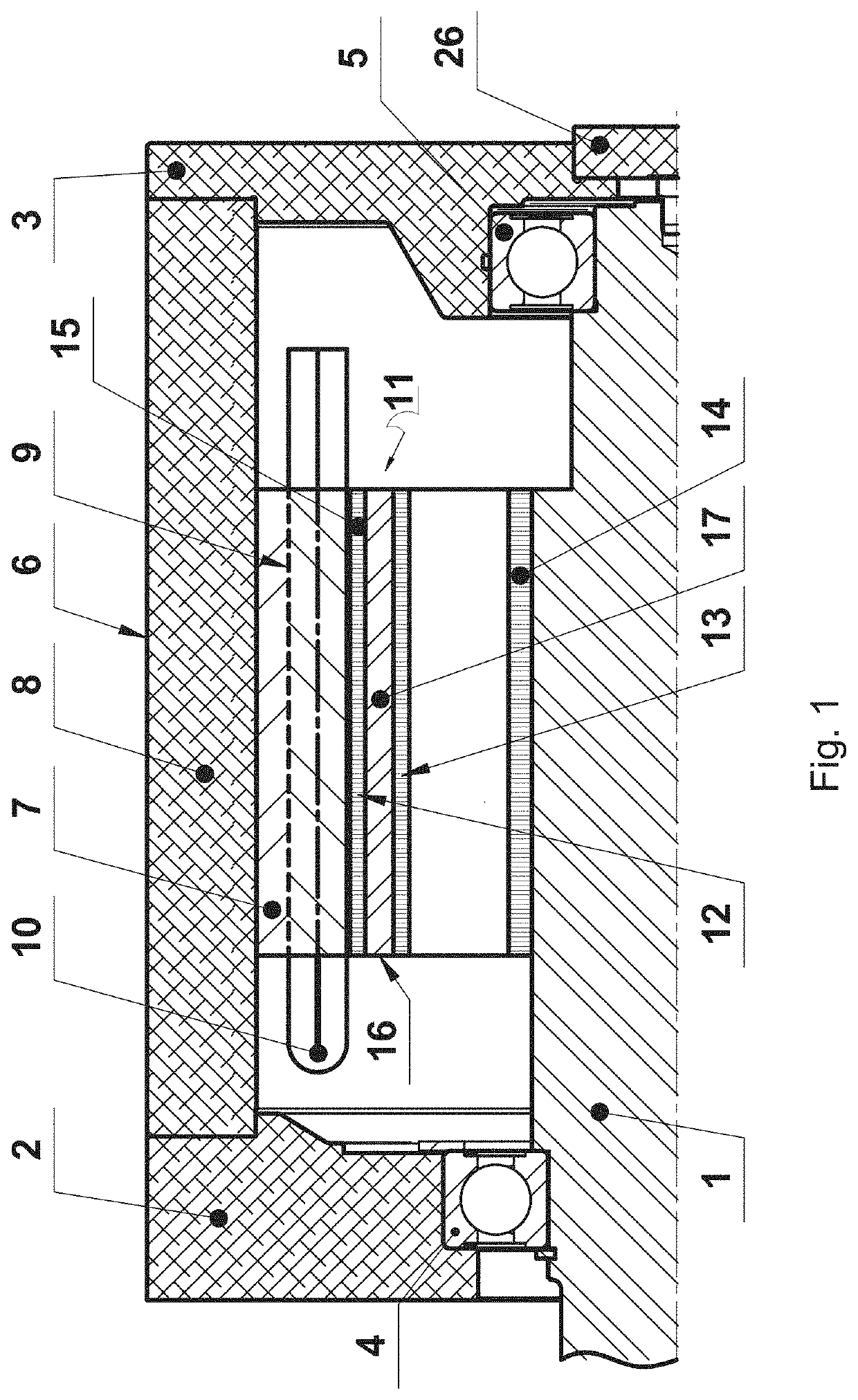
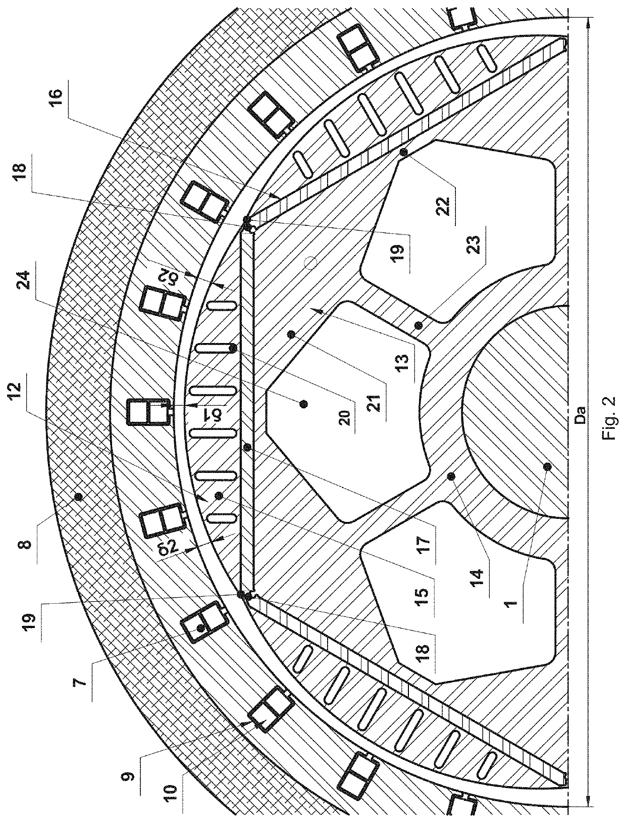
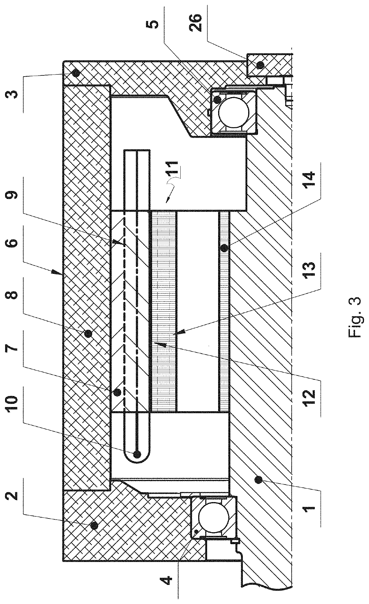
[0022]FIGS. 1 and 2 show a first embodiment of the invention including shaft 1 sustained in front 2 and rear 3 end bells by front 4 and rear 5 bearings. The front end bell 2 and the rear end bell 3 comprise a stator 6 with an inner diameter Da. The stator 6 comprises a stator pack 7 fixedly enclosed by a housing 8. On the inner surface of the stator pack 7 are formed many evenly distributed slots 9. An insulated coil 10 is placed in each slot 9. The stator pack 7 encloses movably an annular rotor 11. The annular rotor 11 comprises an outer steel ring 12, an intermediate steel ring 13 and an inner steel ring 14. The outer steel ring 12 contains sequentially interconnected cut-out parts 15. Each cut-out part 15 is shaped as part of a steel cylinder cut in a plane containing a chord of the cross-section of the cylinder and the axis of the cylindrical surface of each pole does not coincide with the axis of the shaft 1. In the annular rotor 11, under the flat wall of each cut-out part 15...


PUM


Abstract

A brushless electrical machine with permanent magnet excitation, designed for propulsion, in particular of boats, pumps, electric vehicles, for operation as a servomotor, etc. The brushless electrical machine provides increased power at significant reduction of the weight and the inertia moment of its rotor. The rotor (11) comprises an outer (12), intermediate (13) and inner (14) steel rings. The surface of the poles of the rotor (11) is formed by interconnected cut-out parts (15). In the rotor (11), above the permanent magnets (17) are formed elongated axial slots (20). By number of poles 2 p less than 16 and at a diameter of the rotor (11) greater than 0.15 m, the axial slots (16) are divided into two equal parts by a third radial rib (25) with maximum width 0.0025 m, which is located under the middle of the cut-out part (15) and is connecting the intermediate ring (13) to the outer ring (12).

Description

FIELD OF THE INVENTION[0001]The invention relates to a brushless electrical machine with permanent magnet excitation, designed for propulsion, in particular of boats, pumps, electric vehicles, for operation as a servomotor, etc.DESCRIPTION OF PRIOR ART[0002]A brushless electrical machine with permanent magnet excitation is known [1], designed for propulsion of electrical vehicles, including a shaft sustained in front and rear end bells by front and rear bearings. The front and rear end bells envelop a stator containing a stator pack covered by a fixed housing. On the inner surface of the stator is formed a plurality of evenly spaced slots in which a three-phase winding is laid. The stator comprises a movable annular rotor fixed to the shaft. In the rotor are formed at least two poles of permanent magnets, which are inserted into axial slots located near its outer surface. The permanent magnets are located in the rotor in one or more layers. Near the permanent magnets and to the oute...

Claims


Application Information

Patent Timeline
Patent Type & Authority Applications(United States)
IPC IPC(8): H02K1/17H02K21/14H02K1/278
CPCH02K1/17H02K2213/03H02K1/278H02K21/14H02K1/276H02K2201/03H02K1/24H02K29/03Y02E60/16
Inventor POPOV, ENCHO NIKOLOV
Owner ALMOTT GRP AD
Learn More