Compressed air processing system for commercial vehicle

Active Publication Date: 2022-06-23
SEMYUNGTECH CO LTD
View PDF0 Cites 0 Cited by
  • Summary
  • Abstract
  • Description
  • Claims
  • Application Information

AI Technical Summary

Benefits of technology

The present disclosure describes a regeneration system for compressors that improves regeneration efficiency. This is achieved by controlling a valve to increase the pressure of the regeneration sequence valve in the regeneration line and delay the opening time of the regeneration line compared to unloading of the compressor. The system also prevents overpressure in the compressed air supply line, solves the problem of decreased initial regeneration efficiency due to high-pressure compressed air remaining in the supply line, and improves the durability of the unloader valve. Additionally, the system prevents rapid closure of the valves after air movement, simplifies the control logic, reduces manufacturing costs, and minimizes loss of compressed air during regenerating operation.

Problems solved by technology

Such foreign substances such as oil and water in compressed air have a bad influence on systems such as causing breakdown or deteriorating durability of pneumatic systems.

Method used


Image

  • Compressed air processing system for commercial vehicle
  • Compressed air processing system for commercial vehicle

Examples


first embodiment

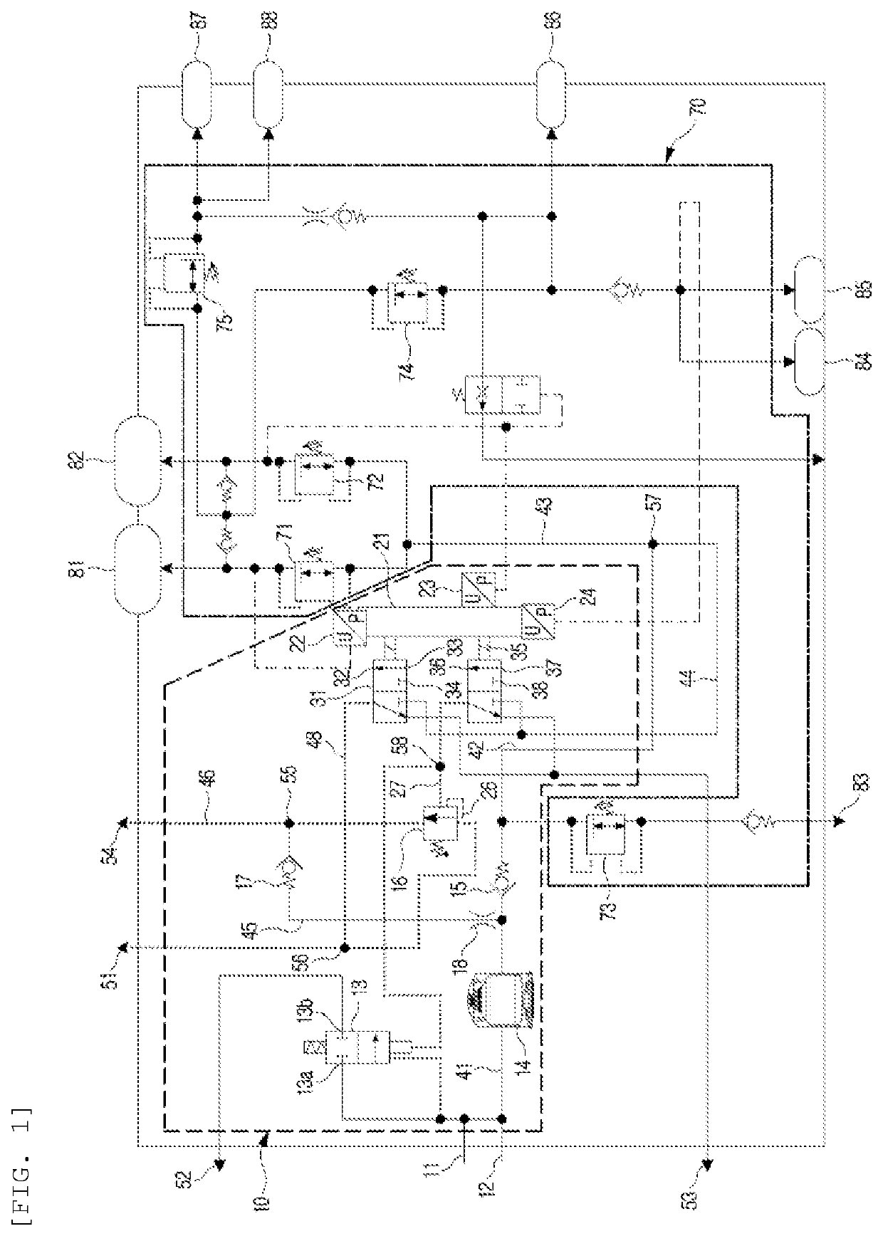
[0039]FIG. 1 shows a compressed air processing apparatus according to the present disclosure. A compressed air processing system 1 according to a preferred embodiment of the present disclosure includes a drier unit 10 and a valve assembly 70. The part indicated by a dashed line at the left side in FIG. 1 shows the drier unit 10 that is supplied with compressed air from a compressor, dries the compressed air through a filter cartridge 14, and then supplies the compressed air to the valve assembly 70. Further, the compressed air processing system 1, as shown at the other side, that is, the part indicated by a dashed dotted line in FIG. 1, may be configured to a valve assembly 70 including valves that supply compressed air from a downstream side of a first supply line 43 to each compressed air consumption system at a divergence point 57.

[0040]As shown in FIG. 1, the compressed air processing system according to a preferred embodiment of the present disclosure is configured to be able t...

second embodiment

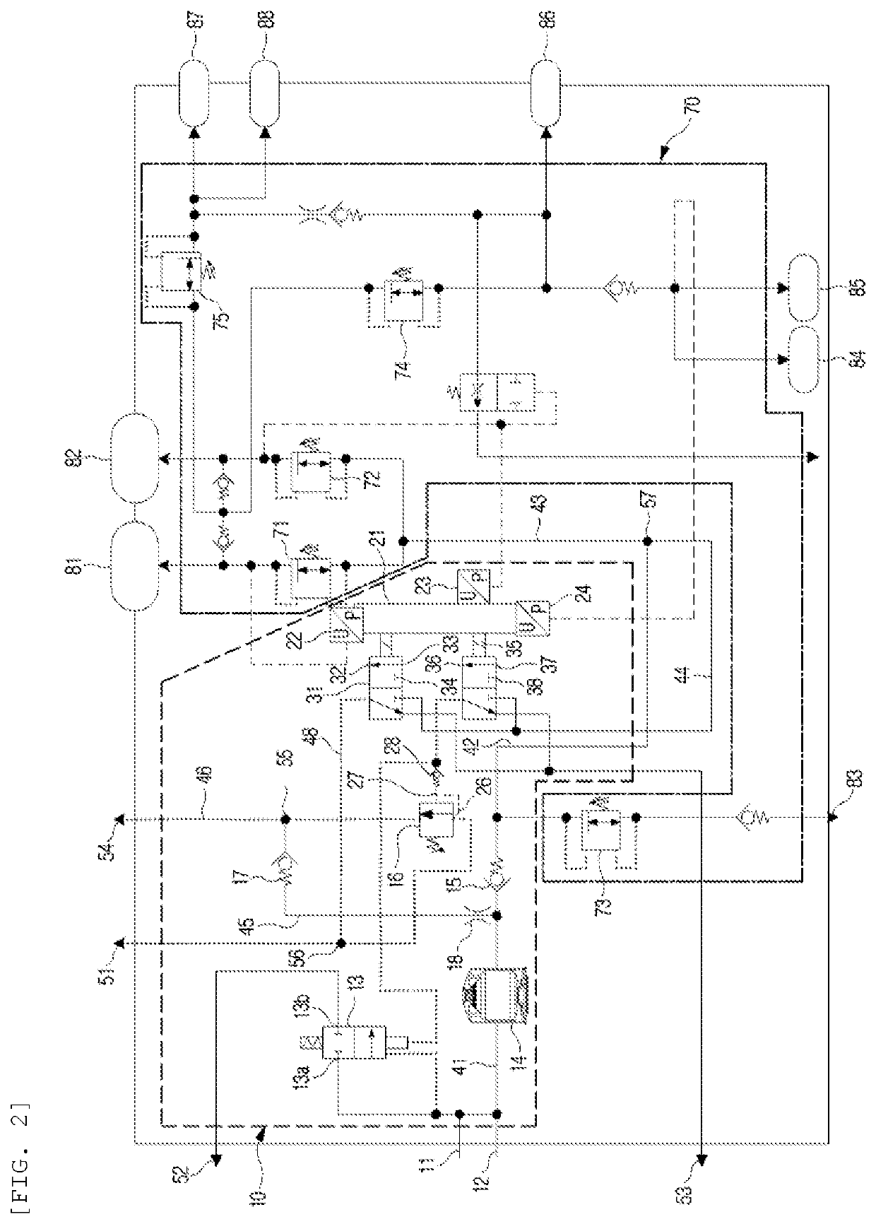
[0077]Meanwhile, the present disclosure is shown in FIG. 2.

[0078]The example of FIG. 2 is substantially the same as the compressed air processing system of the first embodiment except for the structure of the regeneration sequence valve 16, particularly, the structure of the control input line. That is, in FIG. 2, unlike FIG. 1, the second input line 27 that supplies air through the second electronic control valve 35 is connected to the first control input line 26 without being separated from the first control input line 26. Accordingly, a check valve 28 for preventing backflow of air is installed in the second control input line 27. In the compressed air processing system of the second embodiment, the regeneration sequence valve 16 is opened only when the set pressure is reached by the compressed air flowing inside through the first control input line 26 and the second control input line 27, which is the same as the first embodiment. In the embodiment of FIG. 2, there is an effect ...


PUM


Abstract

The present disclosure provides a compressed air processing system of which the operation of supplying compressed air and the regeneration operation can be efficiently controlled by an electronic control unit. In particular, the present disclosure is characterized in that the pressure of a regeneration sequence valve installed in a regeneration line is increased over a set pressure by controlling a valve, which is electronically controlled, to switch, so the opening time of the regeneration line is delayed in comparison to the opening time of an unloader valve, whereby regeneration efficiency is improved.

Description

CROSS-REFERENCE TO RELATED APPLICATION[0001]This application is a Continuation Application of International Application No. PCT / KR2020 / 018820 filed on Dec. 21, 2020, which claims priority to Korean Application No. 10-2020-0178398 filed on Dec. 18, 2020, the entire contents of each of the above-identified applications are hereby incorporated by reference.TECHNICAL FIELD[0002]The present disclosure relates to a compressed air processing system for a commercial vehicle and, more particularly, to a compressed air processing system that supplies compressed air, which is used for the braking system, suspension system, etc. of commercial vehicle, with oil, water, and foreign substance filtered out from the air, and that regenerates an air drier by sending the compressed air backward.BACKGROUND ART[0003]Commercial vehicles are equipped with various operation systems that use air pressure to control the operation of the large and heavy commercial vehicles. For example, a service brake system...

Claims


Application Information

Patent Timeline
IPC IPC(8): B60T13/68B60T17/00B60T13/26
CPCB60T13/683B60T13/26B60T17/002B60T17/004B60G13/10B60T17/00F15B11/06F15B13/02F15B21/041
Inventor MOON, SEONG-WONPARK, SANG-SUN
Owner SEMYUNGTECH CO LTD
Why Eureka
Try Eureka