
Electronic device and method for eye-tracking of user and providing augmented reality service thereof

a technology of eye tracking and electronic devices, which is applied in the field of electronic devices and methods for eye tracking of users and providing augmented reality service thereof, can solve the problems of increasing the weight of electronic devices, the decrease of the comfort of wearing electronic devices, and the increase of the unit price of electronic devices, so as to achieve the effect of increasing the number of cameras

Pending Publication Date: 2022-06-23
SAMSUNG ELECTRONICS CO LTD
View PDF2 Cites 2 Cited by
  • Summary
  • Abstract
  • Description
  • Claims
  • Application Information

AI Technical Summary

Benefits of technology

This patent aims to reduce the cost, weight, and size of an electronic device by reducing the number of cameras within it. Additionally, it aims to increase the device's running time.

Problems solved by technology

As described above, when the number of cameras increases, a volume and weight of the electronic device increase, which may cause a problem in that the wearing comfort of the electronic device decreases and a unit price of the electronic device increases.
Further, there may be a problem in that a running time reduces due to power required to drive the plurality of cameras.
In addition, there may be a problem in that a space for disposing a plurality of cameras is wasted.
In order to integrate the cameras, when components such as prisms or mirrors are added, similar problems may arise in terms of space and weight.

Method used


Image

  • Electronic device and method for eye-tracking of user and providing augmented reality service thereof
  • Electronic device and method for eye-tracking of user and providing augmented reality service thereof
  • Electronic device and method for eye-tracking of user and providing augmented reality service thereof

Examples


Embodiment Construction

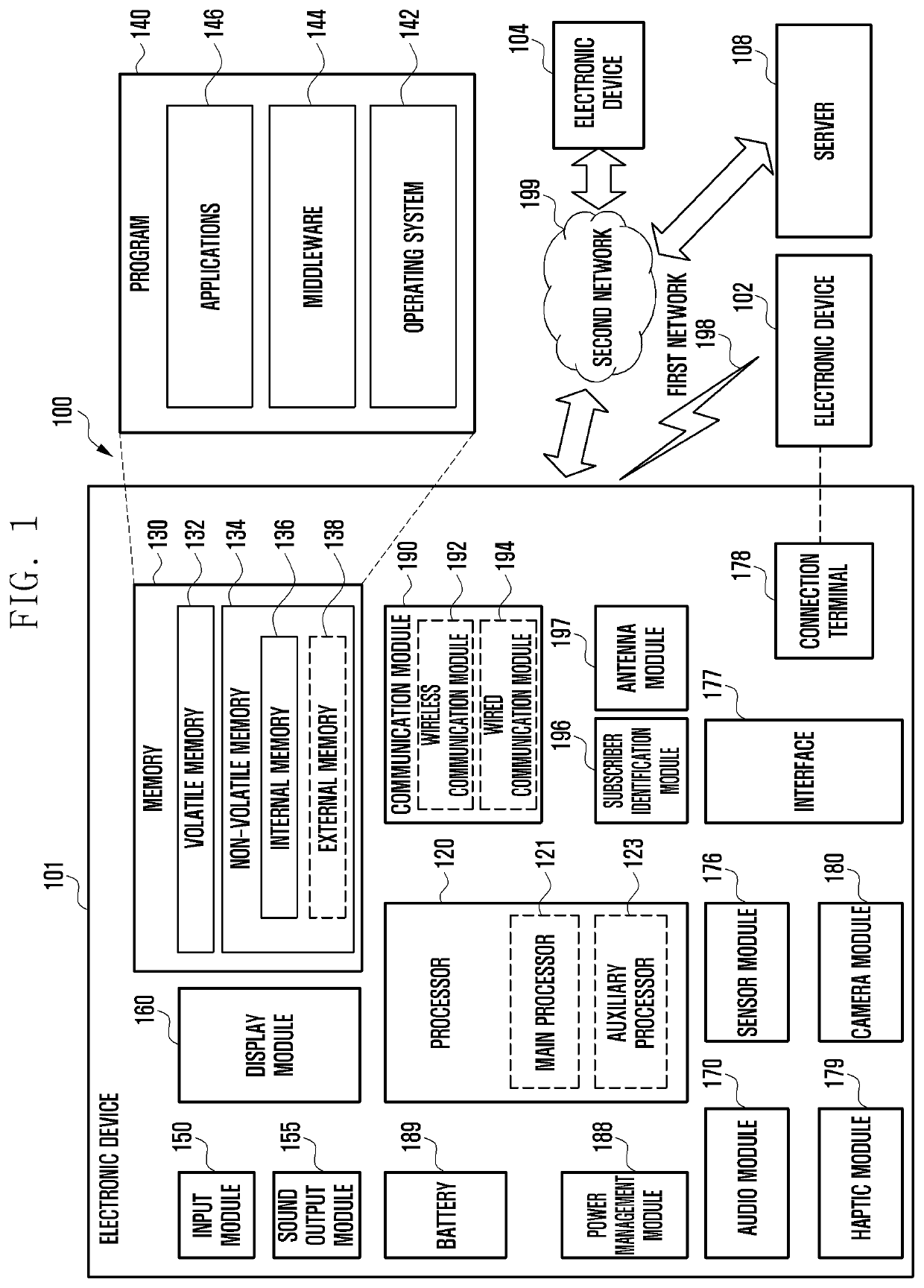
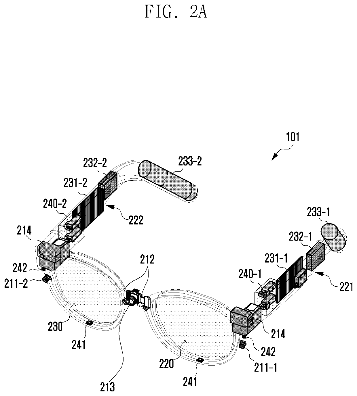
[0028]FIG. 1 is a block diagram illustrating an example electronic device 101 in a network environment 100 according to various embodiments. Referring to FIG. 1, the electronic device 101 in the network environment 100 may communicate with an electronic device 102 via a first network 198 (e.g., a short-range wireless communication network), or at least one of an electronic device 104 or a server 108 via a second network 199 (e.g., a long-range wireless communication network). According to an embodiment, the electronic device 101 may communicate with the electronic device 104 via the server 108. According to an embodiment, the electronic device 101 may include a processor 120, memory 130, an input 1 module 150, a sound output 1 module 155, a display 1 module 160, an audio module 170, a sensor module 176, an interface 177, a connecting terminal 178, a haptic module 179, a camera module 180, a power management module 188, a battery 189, a communication module 190, a subscriber identifi...


PUM


Abstract

According to various embodiments of the disclosure, an electronic device includes: a frame; a glass module comprising a glass supported by the frame; a support rotatably connected to the frame; a display module comprising display circuitry configured to project an image to the glass module; a front camera disposed in at least one of the frame or the support configured to photograph the front of the frame; a light emitting unit comprising light-emitting circuitry configured to radiate light toward the rear of the frame; and an eye tracking camera disposed in the frame configured to photograph the rear of the frame and including a lens assembly including at least one lens, wherein the eye tracking camera is configured to form a field of view (FOV) to include both a left eye and a right eye of a user based on an object distance, which is a distance between the lens assembly and an object, being a first distance corresponding to a distance between the lens assembly and the left eye and / or the right eye of the user wearing the electronic device, wherein an absolute value of a distortion value of the lens assembly is equal to or less than a threshold value capable of tracking a pupil movement of the left eye and the right eye with respect to light incident from a region of interest (ROI) within a certain range from an outermost portion to the inside among regions corresponding to the FOV.

Description

CROSS-REFERENCE TO RELATED APPLICATIONS[0001]This application is a continuation of International Application No. PCT / KR2021 / 019536 designating the United States, filed on Dec. 21, 2021, in the Korean Intellectual Property Receiving Office and claiming priority to Korean Patent Application No. 10-2020-0179278, filed on Dec. 21, 2020, in the Korean Intellectual Property Office, the disclosures of which are incorporated by reference herein in their entireties.BACKGROUNDField[0002]The disclosure relates to an electronic device, and for example, to a wearable electronic device including a camera for implementing augmented reality (AR).Description of Related Art[0003]An electronic device may provide virtual reality (VR) that enables a user to have a real-like experience in a virtual world created by a computer. Further, the electronic device may provide augmented reality (AR) in which virtual information (or object) is added to the real world and mixed reality (MR) in which VR and AR is m...

Claims


Application Information

Patent Timeline
IPC IPC(8): G06F3/01H04N5/247G06T11/00G06T3/40G02B27/01G02B27/00
CPCG06F3/013H04N5/247G06T11/00G06T3/40G02B2027/0134G02B27/0093G02B2027/0138G02B2027/014G02B27/0101G02B27/0172G06F3/011H04N23/90
Inventor SONG, DOUKYOUNGKWAK, HOKEUNJEON, JINA
Owner SAMSUNG ELECTRONICS CO LTD
Learn More