This helps you quickly interpret patents by identifying the three key elements:
Problems solved by technology
Method used
Benefits of technology
Benefits of technology
The invention is about a device that can improve the production of emulsified products, allowing for continuous and mass production. The device can also be made using 3D printing methods, allowing for various shapes to be provided.
Problems solved by technology
However, these methods lead to emulsion drops characterized by a coefficient of size variation, defined as the ratio between the standard deviation of the drop sizes and the mean drop size, of at least about 15%.
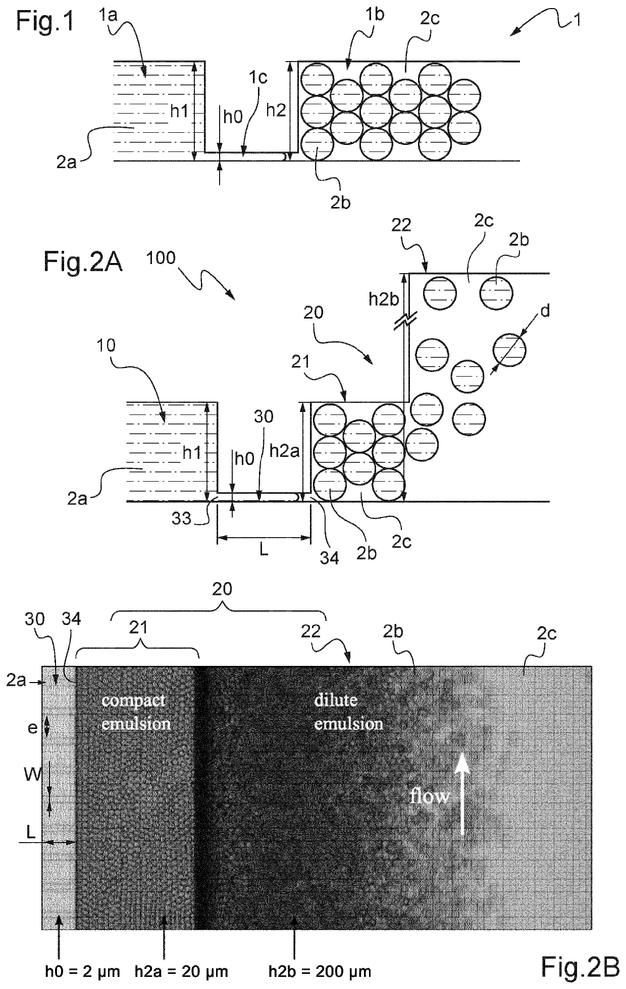
An emulsion which is too concentrated could lead to a detrimental effect on the production of this emulsion: increasing the volume fraction of the phase to be dispersed (i.e. the drops) in the continuous phase increases the viscosity of the emulsion and thus the corresponding pressure losses.
However, flow control can be difficult to use for small drop sizes whose rate of production is relatively low.
Furthermore, the pressure conditions at the first microchannels can be disadvantageous.
Increasing the pressure of the continuous phase in order to avoid clogging the device thus amounts to altering, or even stopping, part of the drop production of the microchannels located upstream.
Method used
Image
Click on the blue label to locate the original text in one second.
Reading with bidirectional positioning of images and text.
Examples
first embodiment
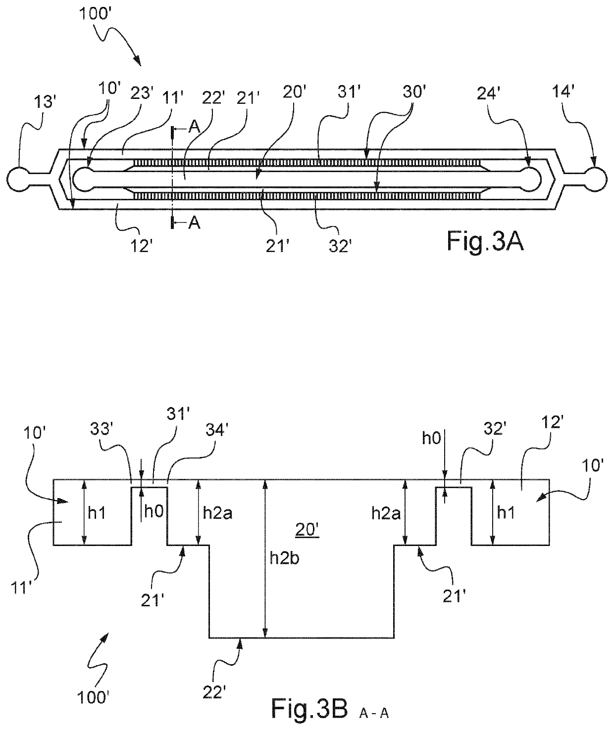
[0150]A diagram of a microfluidic device 100′ for producing an emulsion is shown in FIGS. 3A and 3B (cross-section along the dotted line A-A) compliant with the principle of FIG. 2A.
[0151]In one embodiment, the dimensions of the microfluidic parts of such microfluidic device 100′ can be about 10 cm (length L0)×1 cm (width WO). For example, the height of the device would be the biggest height amongst h1, h2b.
[0152]Microfluidic device 100′ comprises a first channel 10′, a second channel 20′, and two facing arrays 31′,32′ of microchannels 30′ linking the first channel 10′ to the second channel 20′.
[0153]In one embodiment, each array 31′,32′ comprises 1 000 microchannels 30′.
[0154]Each microchannel 30′ has an inlet 33′ from the first channel 10′ and an outlet 34′ to the second channel 20′ (see FIG. 3B).
[0155]The second channel 20′ is, in the present invention, centrally positioned in the device between the two arrays of microchannels 30′.
[0156]Besides, it is straight here.
[0157]The se...
second embodiment
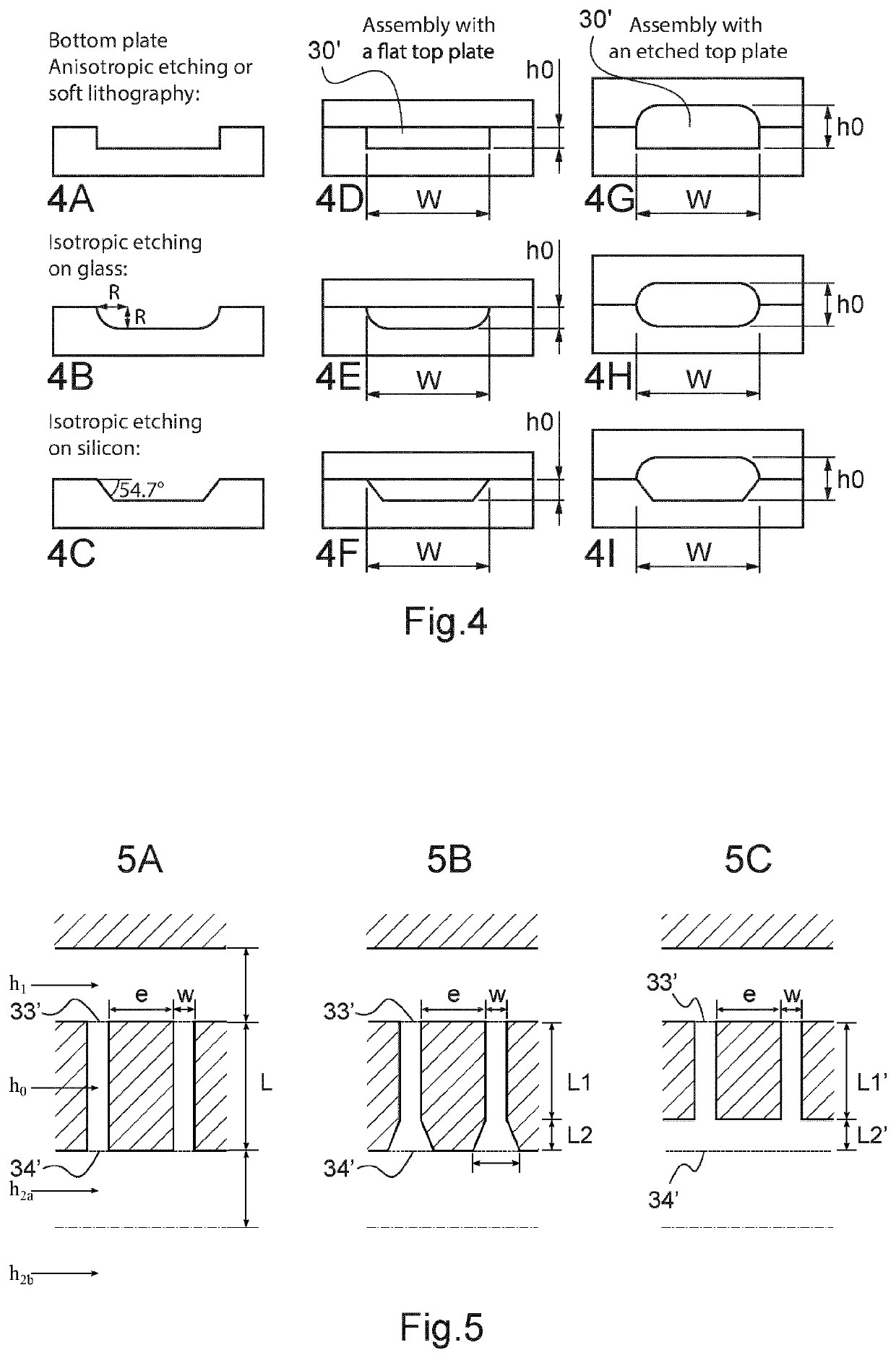
[0186] FIG. 5B shows microchannels having a first part with a constant width W along their length L1 and a second part which is flared along their length L2.
third embodiment
[0187] FIG. 5C shows microchannels having a first part with a constant width W along their length L1′ and a second part which is common to several microchannels along their length L2′, corresponding to coalescence of several microchannels.
[0188]The second parts of the microchannels have a same height h0.
[0189]The phase to be dispersed 2a is decane (which is an alkane composed of a linear chain of ten atoms of carbon (C)), the continuous phase 2c is water with sodium dodecyl sulphate.
[0190]The flows of both phases are controlled by imposing a pressure on each reservoir containing the liquids and which are connected to the corresponding entry ports of the microfluidic device.
[0191]As shown in FIG. 6, oil-in-water drops 2b are formed at the end of the microchannels 30′, forming a compact emulsion having homogeneous size as revealed by the arrangement of the drops in a crystal like fashion.
[0192]The compact emulsion then flows to the central part 22′ ...
PUM
Property
Measurement
Unit
Width
aaaaa
aaaaa
Height
aaaaa
aaaaa
Hydrophilicity
aaaaa
aaaaa
Abstract
Disclosed is an emulsion production microfluidic device which includes: a first channel, including an entry port configured to inject a phase to be dispersed, a second channel, including an entry port configured to inject a continuous phase and an emulsion exit port, and at least one array of microchannels, a height of each of the microchannels being smaller than a height of the first channel; the second channel includes a first part connected to the outlet of each microchannel and at least a second part along the first part, the first part being between the array of microchannels and the second part, the first part having a height greater that the height of each microchannel, and the second part having a height greater than the height of the first part.
Description
TECHNICAL FIELD[0001]The present invention relates to an emulsion production microfluidic device.BACKGROUND OF THE INVENTION[0002]An emulsion is a mixture of at least two liquids that are normally immiscible. By definition, one liquid (called dispersed phase) is dispersed in another (called continuous phase).[0003]There are two main types of emulsion: a direct emulsion which is like an oil-in-water emulsion, wherein the oil is the dispersed phase and water is the continuous phase, and an inverse emulsion which is like a water-in-oil emulsion, wherein water is the dispersed phase and oil is the continuous phase.[0004]The phase to be dispersed can be a mixture of several miscible fluids, a solution of small molecules, macromolecules, amphiphilic or not, or a dispersion of particles, solid or liquid, the latter thus forming a double, or multiple, emulsion, or a combination of the various above-mentioned options.[0005]The continuous phase generally contains one or more surfactants (amph...
Claims
Application Information
Patent Timeline
Application Date:The date an application was filed.
Publication Date:The date a patent or application was officially published.
First Publication Date:The earliest publication date of a patent with the same application number.
Issue Date:Publication date of the patent grant document.
PCT Entry Date:The Entry date of PCT National Phase.
Estimated Expiry Date:The statutory expiry date of a patent right according to the Patent Law, and it is the longest term of protection that the patent right can achieve without the termination of the patent right due to other reasons(Term extension factor has been taken into account ).
Invalid Date:Actual expiry date is based on effective date or publication date of legal transaction data of invalid patent.

