Flying Object, Flying Object System, and Method For Painting Object to Be Painted
- Summary
- Abstract
- Description
- Claims
- Application Information
AI Technical Summary
Benefits of technology
Problems solved by technology
Method used
Image

Examples
first embodiment
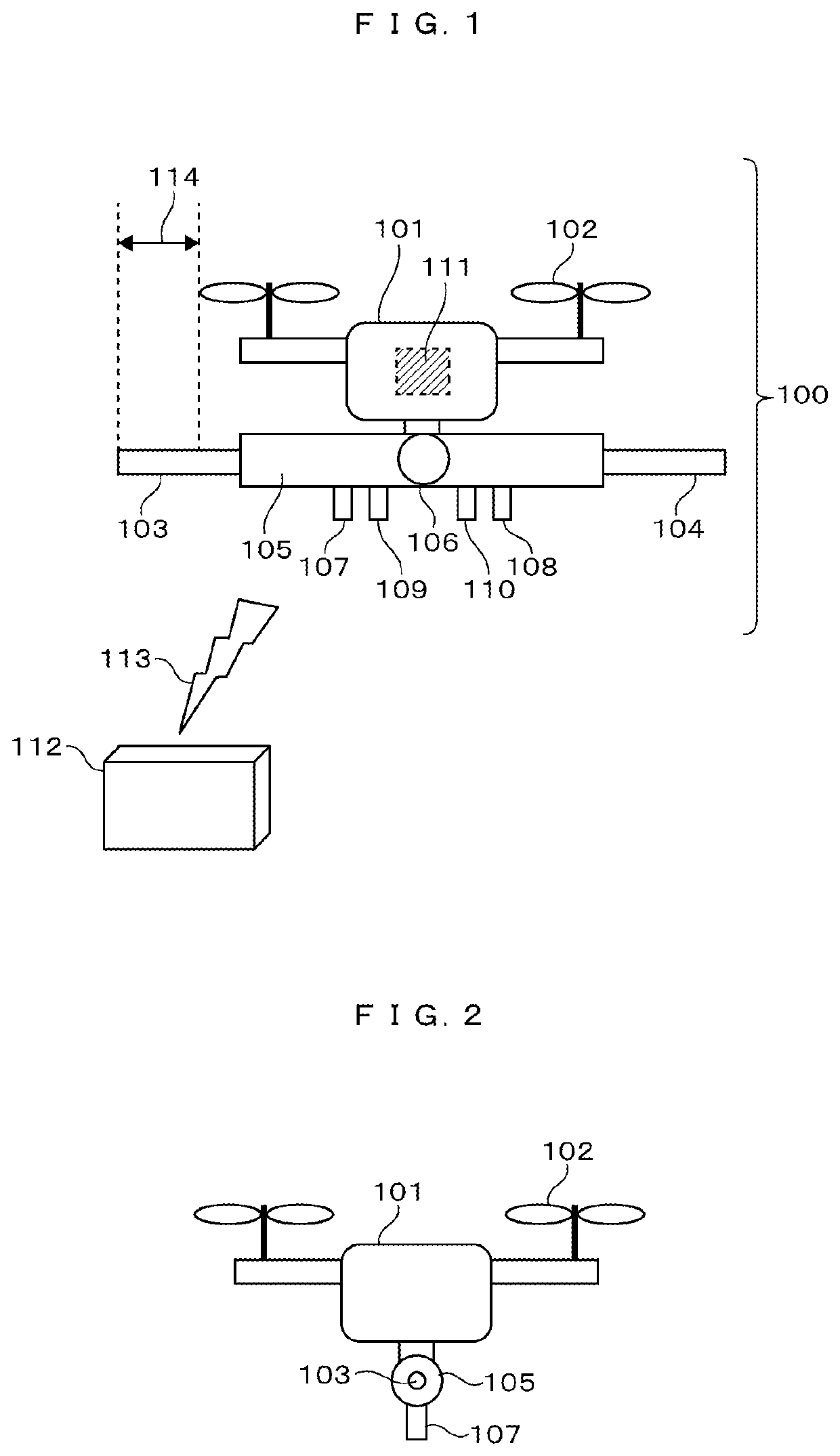
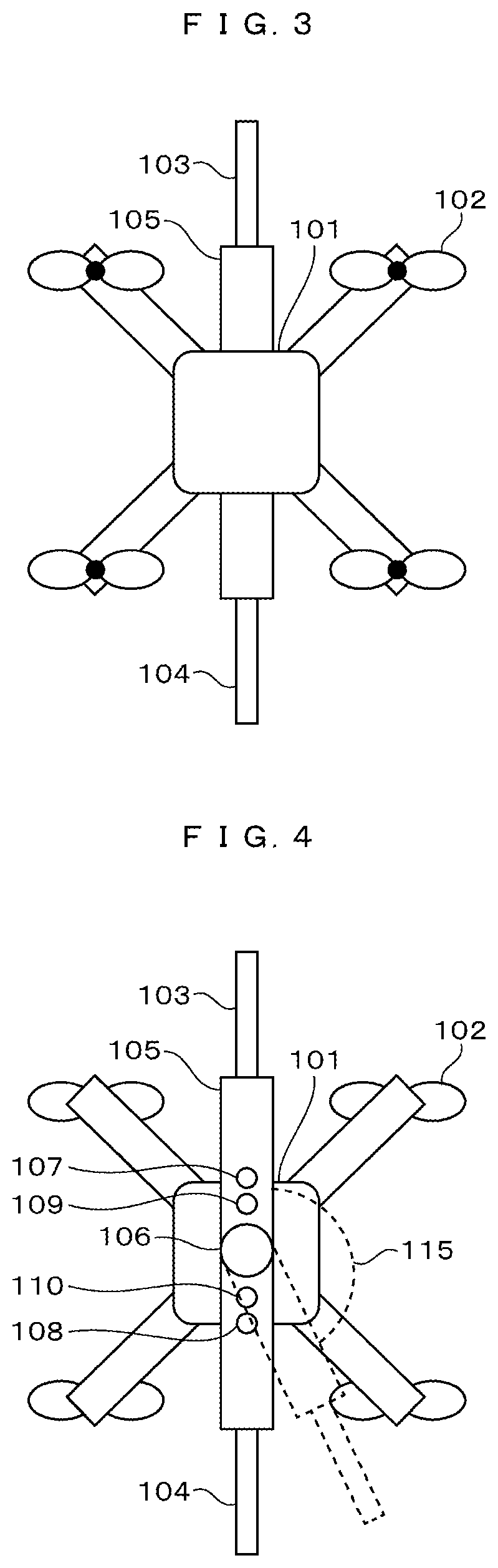
[0022]A configuration of a flying object of a first embodiment will be described with reference to FIGS. 1 to 4.
[0023]A flying object 100 includes a plurality of blades 102 to enable a flying object body 101 to fly. The flying object 100 rotates the blades 102 to fly, and changes the rotation speed to fly while changing the travelling direction and the rising position and speed. A controller 111 installed in the flying object 100 receives radio wave 113 transmitted from an external controller 112, to control the rotation speed of the blades 102. Particularly, the number of the blades 102 is not limited.
[0024]The flying object 100 includes a nozzle 105 in a lower portion of the flying object body 101, the nozzle 105 including a first discharge port 103 and a second discharge port 104. The nozzle 105 includes a movable unit 106. The movable unit 106 changes a direction of the second discharge port 104 as shown by a broken line in FIG. 4 to change an angle 115 formed by the first disch...
second embodiment
[0056]A second embodiment will be described with reference to FIG. 8. The second embodiment is such that the first embodiment is applied to a railway vehicle. FIG. 8 is a side view of a railway vehicle to which painting is applied.
[0057]As shown in FIG. 8, in an exterior wall of a railway vehicle 301, a side surface portion 405 and an upper surface portion that is a ceiling are formed of a processed material obtained by processing a metal sheet. The side surface portion 405 of the railway vehicle 401 is provided with a door portion 403 that is an opening and closing door, and a window portion 304. In addition, the upper surface portion of the railway vehicle 401 is provided with a pantograph 406. The railway vehicle 401 is provided with a wheel 402.
[0058]A paint film is to be formed on the exterior wall of the railway vehicle 401 by the above-described painting. A surface of the metal material is covered with the paint film of the embodiments physically to protect the surface of the...
example 1
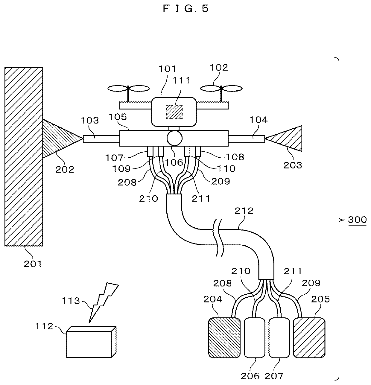
[0061]First, an aluminum sheet was prepared as the object 201 to be painted shown in FIG. 5. Specifically, a 6N01 alloy was used among Al—Mg—Si alloys (6000 series aluminum alloys). The size was 1 m in length×1.2 m in width and 2 mm in thickness.
[0062]First, a blasting process was performed to secure adhesion between an object to be painted and a paint film. The blasting process was performed by blowing crushed steel particles having a particle size of 0.5 mm as a grinding material on the aluminum sheet at a projection speed of 35 m / s. After the blowing was completed, air blowing was performed, and it was visually confirmed that there were no remaining grinding material.
[0063]The aluminum sheet of the object to be painted was erected vertically and installed such that an upper end of the aluminum sheet was located 4 m above the ground. Primer painting was performed to prevent corrosion of the object to be painted. For the primer painting, Uniepoc 30 Primer NC Red Rust Paint Liquid (...
PUM
 Abstract
Description
Claims
Application Information
 - R&D Engineer
- R&D Manager
- IP Professional
- Industry Leading Data Capabilities
- Powerful AI technology
- Patent DNA Extraction
Browse by: Latest US Patents, China's latest patents, Technical Efficacy Thesaurus, Application Domain, Technology Topic.
© 2024 PatSnap. All rights reserved.Legal|Privacy policy|Modern Slavery Act Transparency Statement|Sitemap