Hydraulic brake system

a brake system and hydraulic technology, applied in the direction of brake systems, braking components, transportation and packaging, etc., can solve the problems of imposing a heavy load on the auxiliary power source, affecting the operation of the power source, and requiring large curren

Pending Publication Date: 2022-07-21
TOYOTA JIDOSHA KK +1
View PDF0 Cites 0 Cited by
  • Summary
  • Abstract
  • Description
  • Claims
  • Application Information

AI Technical Summary

Benefits of technology

The present patent is about a hydraulic brake system that has two brake systems, which can still operate even if the main power source fails. The system includes a first pump device that is driven when the accumulator pressure is low, but this can cause a large inrush current and adversely affect the controller and other on-vehicle systems. To solve this problem, the system is designed to continuously drive the first pump device, even if the accumulator pressure is low. This prevents the adverse impact on the controller and other systems. Additionally, when the main power source fails, the system automatically switches to the auxiliary power source and drives the motor continuously, reducing the number of inrush currents and voltage drops. The system can also be configured to cooperate with the first system and supply the working fluid to the wheel brake device at a higher pressure, allowing for a more effective braking force.

Problems solved by technology

It is, however, conceivable that the power source may fail to operate.
When the first pump device starts to be driven, a large current is required.
In the intermittent driving of the first pump device, the start of driving the first pump device is repeated, thus imposing a heavy load on the auxiliary power source in a state in which the electricity is being supplied from the auxiliary power source.
That is, in a case where the auxiliary power source includes a secondary battery, a capacitor or the like, a large inrush current that flows in a state in which the charged amount of the auxiliary power source is small leads to a large drop in the voltage of the auxiliary power source.
This voltage drop may adversely influence an operation of a controller of the first system and operations of on-vehicle systems other than the first system and the second system if the auxiliary power source is supplying the electricity to the other on-vehicle systems.
If the first pump device of the first system is continuously driven when the failure occurs in the main power source, the accumulator pressure may become excessively high.

Method used


Image

  • Hydraulic brake system
  • Hydraulic brake system
  • Hydraulic brake system

Examples


Embodiment Construction

[0038]Referring to the drawings, there will be explained in detail a hydraulic brake system according to one embodiment of the present disclosure. It is to be understood that the present disclosure is not limited to the details of the following embodiment but may be embodied based on the forms described in Various Forms and may be changed and modified based on the knowledge of those skilled in the art.

A. Configuration of Hydraulic Brake System

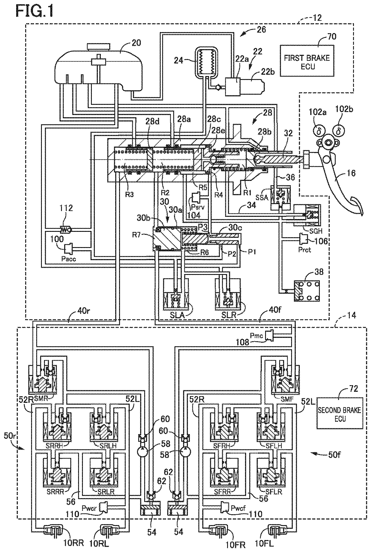
[0039]Referring to a hydraulic circuit diagram of FIG. 1, there will be explained a configuration of a hydraulic brake system according to one embodiment of the present disclosure. The hydraulic brake system is configured to apply a braking force to each of four wheels of a vehicle, i.e., front right and left wheels and rear right and left wheels. As apparent from FIG. 1, the hydraulic brake system includes wheel brake devices 10FL, 10FR, 10RL, 10RR (hereinafter each referred to as “wheel brake device 10” where appropriate) respectively provide...


PUM


Abstract

A hydraulic brake system for a vehicle, including: a wheel brake device configured to generate a braking force based on a pressure of a working fluid; a first brake system including a high-pressure source device including an accumulator and a first pump device that is driven intermittently such that a pressure of the working fluid in the accumulator is not lower than a set lower limit pressure and not higher than a set upper limit pressure; a second brake system including a second pump device; and a main power source that supplies electricity to the first and second brake systems, wherein the hydraulic brake system includes an auxiliary power source that supplies electricity to the first brake system when a failure occurs in the main power source, and wherein the first pump device is continuously driven when the failure occurs irrespective of the pressure in the accumulator.

Description

CROSS REFERENCE TO RELATED APPLICATION[0001]The present application claims priority to Japanese Patent Application No. 2021-005816, which was filed on Jan. 18, 2021, the disclosure of which is herein incorporated by reference in its entirety.BACKGROUNDTechnical Field[0002]The following disclosure relates to a hydraulic brake system to be installed on a vehicle.Description of Related Art[0003]A hydraulic brake system for a vehicle as disclosed in Patent Document 1 (Japanese Patent Application Publication No. 2020-32962) has been proposed, for instance. The disclosed hydraulic brake system includes a wheel brake device provided for each wheel of the vehicle and two brake systems that independently or cooperatively supply a working fluid to each wheel brake device.SUMMARY[0004]The hydraulic brake system receives electricity typically from a power source. It is, however, conceivable that the power source may fail to operate. Some measures to deal with a failure of the power source impro...

Claims


Application Information

Patent Timeline
Patent Type & Authority Applications(United States)
IPC IPC(8): B60T8/172B60T13/74B60T8/88B60T7/04B60T8/40B60T17/22B60T8/26B60T13/14B60T13/68B60T13/66F16D65/18F16D121/24F16D55/226F16D125/40
CPCB60T8/172F16D2125/40B60T8/885B60T7/042B60T13/741B60T8/4081B60T17/221B60T8/267B60T8/4077B60T13/146B60T13/686B60T13/662F16D65/183B60T2270/414B60T2270/402F16D2121/24F16D55/226B60T13/745B60T13/148B60R16/033B60T17/02B60T17/18B60T2270/413B60T17/22
Inventor OKANO, TAKAHIROMIZOO, SHUNKUZUYA, KEN
Owner TOYOTA JIDOSHA KK
Why Eureka
Try Eureka