
Systems and methods for cleaning surfaces

a technology for cleaning surfaces and systems, applied in the direction of cleaning equipment, carpet cleaners, cleaning using liquids, etc., can solve the problems of requiring a relatively large amount of time to dry the flooring, the surface may become (or appear to become) dirty relatively soon, and the conventional cleaning attachment can be relatively difficult to use effectively

Pending Publication Date: 2022-07-28
Z INTPROP HLDG CO LLC
View PDF0 Cites 7 Cited by
  • Summary
  • Abstract
  • Description
  • Claims
  • Application Information

AI Technical Summary

Benefits of technology

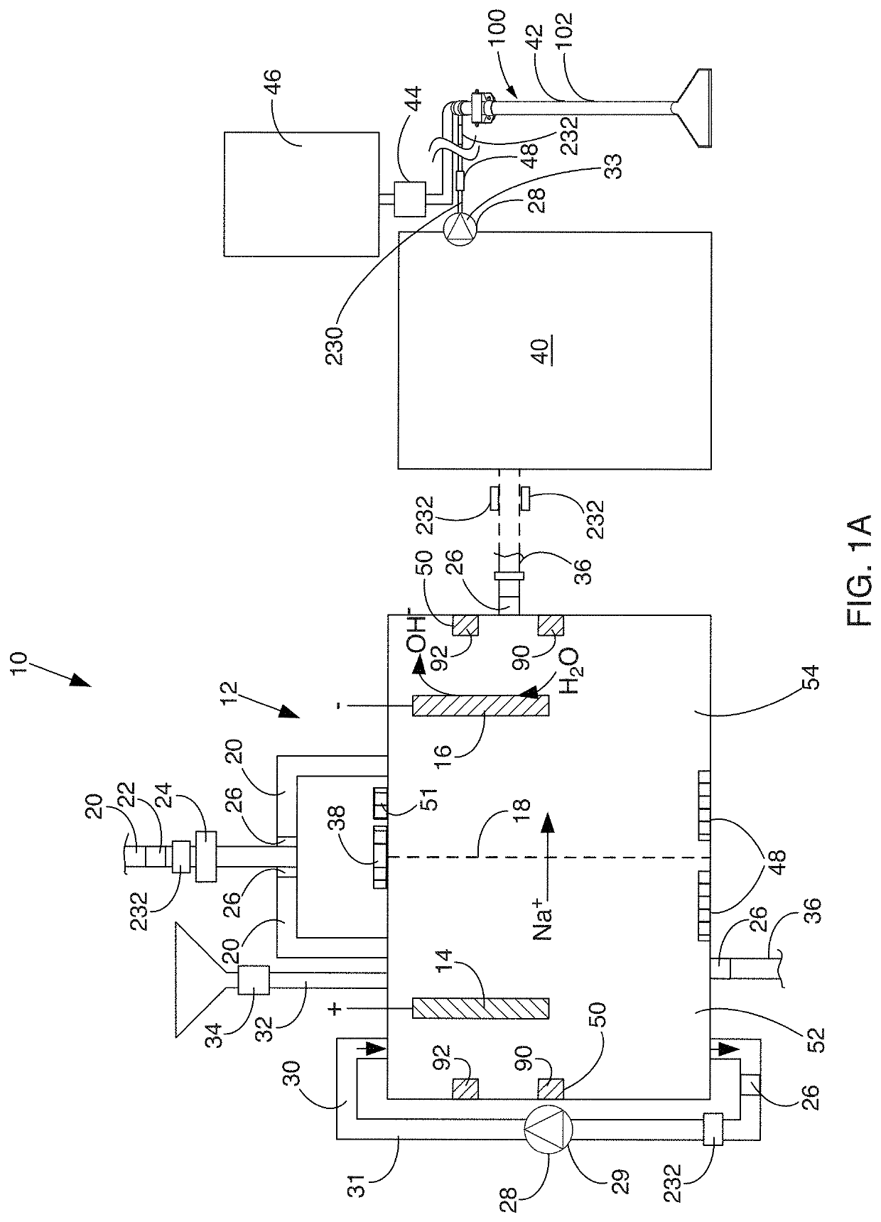
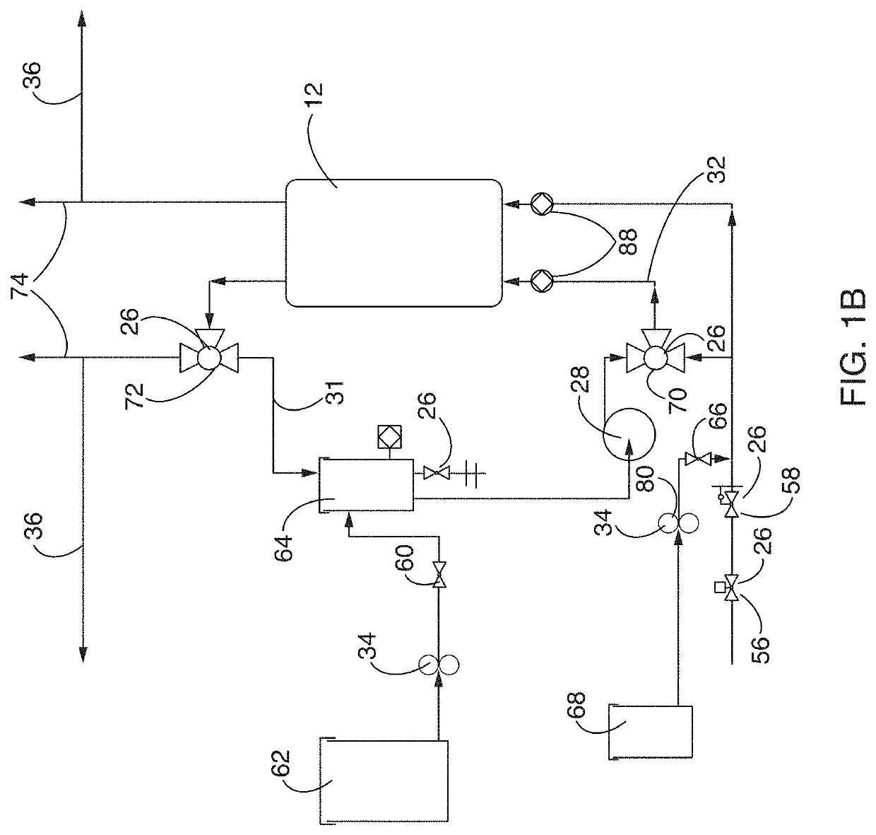
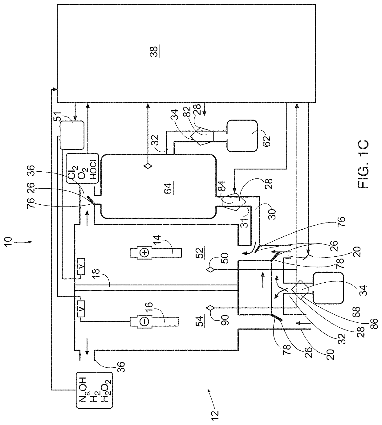
The patent describes a system and method for making electrolyzed alkaline water and electrolyzed oxidizing water through an electrolytic cell. The system allows the two fluids to flow past each other and create a vortex flow, which improves their cleaning effectiveness, binding strength, and chemical reactivity. This leads to better shelf life and a more effective cleaning or disinfecting function, without necessarily reducing water consumption. The technical effect of this system is to provide a more effective and efficient way to make electrolyzed fluids for cleaning and disinfecting purposes.

Problems solved by technology

While these cleaning attachments may be useful at cleaning flooring, such attachments are not necessarily without their shortcomings.
Accordingly, in some cases, it may require a relatively large amount of time to dry the flooring that has been cleaned with a conventional device.
Moreover, as some conventional devices may leave undesirable amounts of cleaning agents (which can attract dirt) on the surface being cleaned, such a surface may become (or may appear to become) dirty relatively soon after being cleaned.
Additionally, some conventional cleaning attachments can be relatively difficult to use effectively.
Moreover, some conventional cleaning attachments can wear out relatively quickly.
Thus, while techniques currently exist that are used to clean flooring, challenges still exist, including those listed above.

Method used


Image

  • Systems and methods for cleaning surfaces
  • Systems and methods for cleaning surfaces
  • Systems and methods for cleaning surfaces

Examples


examples

[0392]In one example of conditioning fluid, two samples of electrolyzed alkaline water were prepared (e.g., using the system 10). While the alkaline water in the petri dish 246 of FIG. 12O was otherwise untreated, the alkaline water in the petri dish 246 of FIG. 12P was conditioned by being run through the hoses 236 and 238 of FIG. 12N one time. The two different fluids were then placed in the petri dishes along with three hydrocarbon stained substrates 248. After twenty hours of sitting in their respective solutions, the hydrocarbon stained substrates 248 had varying appearances. In particular, hydrocarbons in the substrates 248 of FIG. 12P had congregated into more concentrated locations (e.g., resembling micelles). As a result, it is apparent that alkaline water treated in the double helix system of FIG. 12N can be better at capturing oils (e.g., for pulling then from carpets and / or other materials). Moreover, additional test results of conditioned alkaline water are set forth in...


PUM


Abstract

While the described wand can include any suitable component, in some cases, it includes a wand head having a vacuum port with a front face and a back face, a jet port that is coupled at the back face of the vacuum port, and a jet that is coupled to the jet port, the jet being configured to spray effluent through the vacuum port to a surface to be cleaned. In some cases, the front face includes a first jog that extends from a front side of the front face and across a width of the front face. In some cases, the second face includes a second jog that extends across a width of the back face of the vacuum port such that the second jog extends into the vacuum port and defines a second recess at a back side of the back face. Additional implementations are also described herein.

Description

CROSS-REFERENCE TO RELATED APPLICATION[0001]This application claims priority to U.S. Provisional Patent Application Ser. No. 63 / 142,383, filed Jan. 27, 2021, and entitled “SYSTEMS AND METHODS FOR CLEANING SURFACES” (Attorney Docket No. 11623.109); moreover, this is a continuation-in-part application of, and claims priority to, U.S. patent application Ser. No. 17 / 373,646 (Attorney Docket No. 11623.111), filed Jul. 12, 2021, and entitled SYSTEMS AND METHODS FOR PROVIDING A WAND FOR A FLOOR CLEANING APPARATUS; which claims priority to U.S. patent application Ser. No. 16 / 572,471 (now U.S. Pat. No. 11,058,275) (Attorney Docket No. 11623.83), filed Sep. 16, 2019, and entitled SYSTEMS AND METHODS FOR PROVIDING A WAND FOR A FLOOR CLEANING APPARATUS; which claims priority to U.S. patent application Ser. No. 15 / 448,323 (now U.S. Pat. No. 10,413,147) (Attorney Docket No. 11623.20), filed Mar. 2, 2017, and entitled SYSTEMS AND METHODS FOR PROVIDING A WAND FOR A FLOOR CLEANING APPARATUS; and whi...

Claims


Application Information

Patent Timeline
Patent Type & Authority Applications(United States)
IPC IPC(8): A47L11/40A47L11/30A47L11/34
CPCA47L11/4044A47L11/4088A47L11/408A47L11/34A47L11/30B08B5/02A47L13/17A47L11/4083C02F1/4618B08B5/04B08B2203/0229B08B3/026B08B3/14
Inventor KARREN, GAYLORD M.STONE, JAMES K.HOPKINS, JOHN M.SHUPE, WILLIAM R.
Owner Z INTPROP HLDG CO LLC
Learn More