
Dark-Colored, Low-Expansion Fillers

a filler, low-expansion technology, applied in the field of glass frit, can solve the problems of enamel deformation, affecting the properties of enamel, and deformation of the bond between the enamel and the substrate,

Pending Publication Date: 2022-07-28
FERRO CORP
View PDF0 Cites 0 Cited by
  • Summary
  • Abstract
  • Description
  • Claims
  • Application Information

AI Technical Summary

Benefits of technology

The patent text describes a glass frit system that can be used to create colored enamel on a substrate. The system includes a vehicle, glass frit, a colored CTE modifier, and optionally pigments. The colored CTE modifier can be a modified material such as Al2TiO5, Mg2Al4Si5O18, or Perovskite type materials. By applying this system to the substrate and firing it, a colored enamel can be formed. The technical effect of this invention is to provide a reliable and effective method for creating colored enamel on a variety of substrates.

Problems solved by technology

This interfacial stress may cause a degradation in the bond between the enamel and the substrate, and may cause the enamel to craze, fracture, or de-bond from the substrate.
However, modifiers, pigments, and fillers can interact with the glass components during the firing and affect the enamel's properties.
These components often increase the required enamel firing temperature, which can be detrimental to the substrate upon which the enamel is formed.
In general, the glasses used in glass frit systems can aggressively attack, leach, or dissolve the other components to some degree during the enamel firing process.
This affects primarily the surface of the glass particles, typically inhibiting their fusion and flow characteristics.
Unfortunately, any increase in the amount of pigment included in the glass frit system may have a significant negative impact on various characteristics (e.g. further increase the flow temperature) of the glass frit system or of the fired enamel.

Method used


Image

  • Dark-Colored, Low-Expansion Fillers

Examples


examples

[0034]Table 4 shows the compositions of PBrookite-structured colored CTE modifier examples. In examples 1-11, the raw materials were intimately mixed and the intimate mixture was fired at high temperature to form the colored CTE modifiers. Comparative example 1 was fired at 1450° C. for 60 hours to produce phase pure material. Partial substitution of Al with Fe, as in Examples 2 and 3, could be used to lower the firing temperature needed for synthesis to the range of 1350 to 1400° C. Substitutions of Cr for Al in any proportion without co-substitutions did not result in the formation of the PBrookite structure, as in Example 5. Provided that Al and Fe are present, Cr, Mn and Co can be added in attempts to neutralize the brown color of the materials from Examples 2 and 3. These doubly substituted trials appear as Examples 6 to 11 in Table 4.

TABLE 4Pseudo-Brookite ExamplesExampleFormulationSingle PhaseColor1-comparativeAl2TiO5YesWhite2Al1.5Fe0.5TiO5YesBrown3AlFeTiO5YesBrown4Fe2TiO5Alm...


PUM

PropertyMeasurementUnit
wt. %aaaaaaaaaa
wt %aaaaaaaaaa
CTEaaaaaaaaaa

Abstract

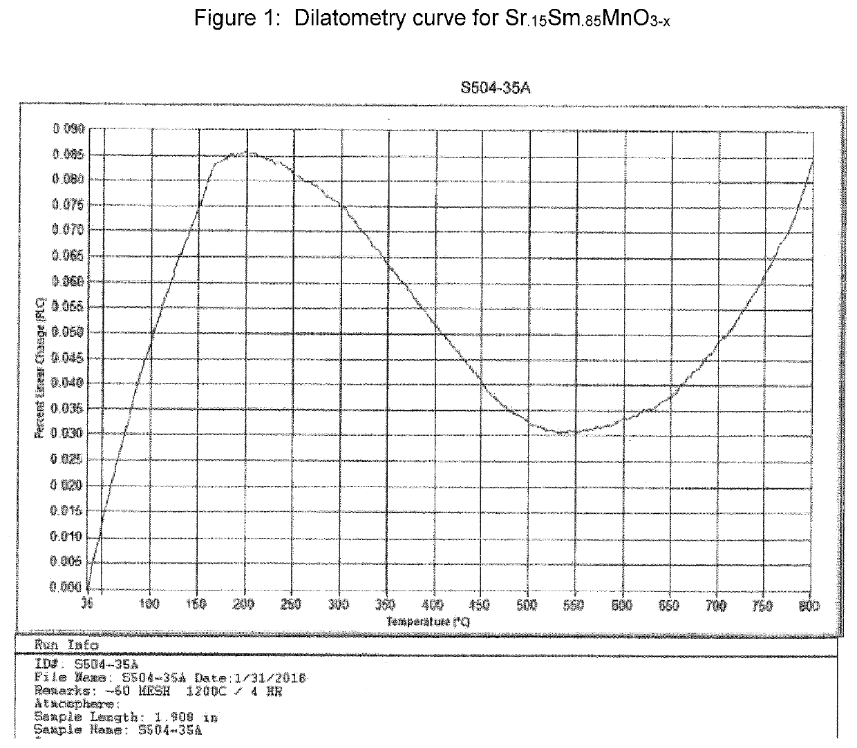
Colored CTE modifiers may be added to a glass frit system to modify the CTE of a resulting fired enamel. The CTE modifier is colored. The colored CTE modifier may include a modified Pseudo-Brookite type material having a formula Al2TiO5, where Al and / or Ti are partially substituted with one or more coloring ions including Fe, Cr, Mn, Co, Ni, and Cu; a modified Cordierite type material having a formula Mg2Al4Si5O18, wherein Mg and / or Al is partially substituted with one or more of the coloring ions; a Perovskite type material having a formula Sm1−xSrxMnO3−δ, where x=0.0-0.5 and δ=0.0-0.25, or a modified version of the Perovskite type material wherein Sr is partially substituted with Ba and / or Ca; a modified magnesium pyrophosphate type material having a formula Mg2P2O7 wherein Mg is substituted with Co and / or Zn ions; or combinations thereof.

Description

BACKGROUND[0001]Glass frit systems are applied to various substrates and fired thereon to form an enamel that is bonded to the surface of the substrate. The fired enamel may be used to modify a characteristic, e.g. the appearance, of the substrate. If the coefficient of thermal expansion (CTE) of the fired enamel does not closely match that of the substrate, a significant interfacial stress will develop between the enamel and the substrate during the cooling cycle of the enamel firing process. This interfacial stress may cause a degradation in the bond between the enamel and the substrate, and may cause the enamel to craze, fracture, or de-bond from the substrate.[0002]Ferro Corporation and other companies have long practiced the use of CTE modifiers, additives whose primary purpose is to enable modification of the enamel's overall CTE while minimizing its effect on the other enamel properties or the required firing profile. These additives serve to reduce the CTE difference between...

Claims


Application Information

Patent Timeline
Patent Type & Authority Applications(United States)
IPC IPC(8): C03C8/20C03C8/04C03C8/16C03C8/10
CPCC03C8/20C03C8/10C03C8/16C03C8/04C03C8/14C03C2205/00
Inventor AXTELL, III, ENOS A.MALONEY, JOHN J.GLEASON, CODY J.SRIDHARAN, SRINIVASANSAKOSKE, GEORGE E.
Owner FERRO CORP
Learn More