Ground information detection method, ground information detection system, ground information detection program, and profile

Pending Publication Date: 2022-07-28
MR SUPPORT INC
View PDF0 Cites 0 Cited by
  • Summary
  • Abstract
  • Description
  • Claims
  • Application Information

AI Technical Summary

Benefits of technology

[0065]As described above, according to the present invention, it is possible to accurately specify the repair location where a depression is formed on the road surface. Furthermore, it is possible to accurately detect the amount of depression on the road surface and to accurately predict the material cost needed for repair to eliminate the depression of the road surface at the time of start of repair. It is also possible to accurately predict the cutting volume when repair is conducted using the cutting overlay method.
[0066]According to the present invention, it does not need to take

Problems solved by technology

In order to repair a road, it is necessary to inspect the uneven state of the road surface and, conventionally the road surface is visually inspec

Method used


Image

  • Ground information detection method, ground information detection system, ground information detection program, and profile
  • Ground information detection method, ground information detection system, ground information detection program, and profile
  • Ground information detection method, ground information detection system, ground information detection program, and profile

Examples


Example

First Embodiment

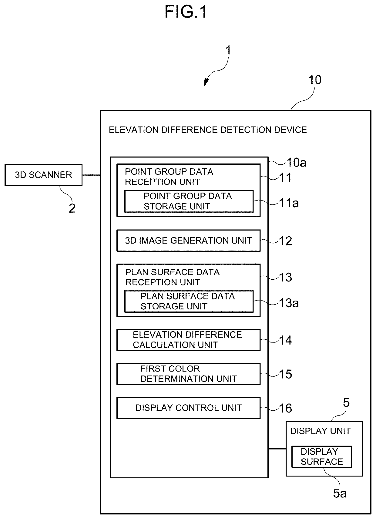
[0098]An elevation difference detection system 1 serving as a ground information detection system according to an embodiment of the present invention includes a 3D scanner 2 (three-dimensional scanning device) and an elevation difference detection device 10 that is wirelessly connected to the 3D scanner 2.

[0099]The 3D scanner 2, installed at a known point, emits laser light and thus acquires each point on and around a road surface as point group data (a set of elevations having plane position coordinates) obtained as three-dimensional coordinates and supplies the point group data to the elevation difference detection device 10. The 3D scanner 2 emits line laser light for example in a vertical direction and a horizontal direction to a measurement target (road surface) and measures the time it takes for a laser pulse to travel back and forth between a measurement point on the measurement target and a sensor so as to obtain the distance to the measurement point. The poi...

Example

Second Embodiment

[0145]An elevation difference detection system 101 according to a second embodiment is different from the elevation difference detection system 1 according to the first embodiment in that, while an inspector determines the state of the road surface based on the image having a plurality of colors added thereto in accordance with the magnitude of the elevation difference according to the first embodiment, the elevation difference detection system 101 automatically determines the state of the road surface according to the second embodiment. As for the elevation difference detection system 101 according to the second embodiment, detailed descriptions are omitted for the same configuration as that of the elevation difference detection system 1 according to the first embodiment.

[0146]As illustrated in FIG. 15, the elevation difference detection system 101 according to the present embodiment includes the 3D scanner 2 (three-dimensional scanning device) and an elevation dif...

Example

Third Embodiment

[0209]A longitudinal profile generation system 201 serving as a ground information detection system according to an embodiment of the present invention includes a 3D scanner 202 (three-dimensional scanning device) installed at a known point, a UAV 203 (unmanned aerial vehicle) that is an unmanned aircraft serving as a capturing device, and a longitudinal profile generation device 210 that is wirelessly connected to the 3D scanner 202 and the UAV 203.

[0210]The 3D scanner 202 emits laser light to thus acquire each point on and around the road surface as point group data (a set of elevations having plane position coordinates) generated as three-dimensional coordinates and feeds the point group data to the longitudinal profile generation device 210. The 3D scanner 202 emits line laser light for example in a vertical direction and a horizontal direction to a measurement target (road surface) and measures the time it takes for a laser pulse to travel back and forth between...


PUM


Abstract

The ground information about the uneven state of the ground is easily detected. A ground information detection method according to the present invention includes: a point group data acquisition step for acquiring point group data generated as three-dimensional coordinates for each point on the ground with laser light emitted from a three-dimensional scanning device installed at a known point; and a ground information detection step for detecting ground information about an uneven state of the ground using the point group data acquired at the point group data acquisition step.

Description

TECHNICAL FIELD[0001]The present invention relates to a ground information detection method, a ground information detection system, a ground information detection program, and a profile for detecting for example an uneven state of a road surface.BACKGROUND ART[0002]Conventionally, when there is a damage such as depression on the surface of asphalt pavement, which forms the surface layer of a road, etc., repair is conducted using, for example, a cutting overlay method. According to this repair method, a surface layer portion of the existing asphalt pavement is cut and removed with a road surface cutting machine, and then new asphalt is laid to construct a new surface layer.[0003]In order to repair a road, it is necessary to inspect the uneven state of the road surface and, conventionally the road surface is visually inspected by an inspector; however, the work of inspecting the road surface and measuring the amount of depression by each inspector is very complicated. Therefore, there...

Claims


Application Information

Patent Timeline
IPC IPC(8): E01C23/01G06T17/05G06V10/56G06T7/90G06V20/10G06T7/70G06T17/20G06T19/20G01S17/89
CPCE01C23/01G06T17/05G06V10/56G06T7/90G06V20/182G06T7/70G06T2219/2012G06T19/20G01S17/89G06T2210/56G06T2207/10028G06T2207/10024G06T17/20G06V2201/12G06T7/001G06T2207/30132G01C15/00
Inventor KUSAKI, SHIGEOMORI, TAKAMITSU
Owner MR SUPPORT INC
Why Eureka
Try Eureka