Time of flight sensing

Pending Publication Date: 2022-07-28
AMS INT
View PDF0 Cites 0 Cited by
  • Summary
  • Abstract
  • Description
  • Claims
  • Application Information

AI Technical Summary

Problems solved by technology

A disadvantage of this arrangement is that the frame rate, that is the rate at which the output from t

Method used


Image

  • Time of flight sensing
  • Time of flight sensing
  • Time of flight sensing

Examples


Embodiment Construction

[0035]Some embodiments of the disclosure will now be described by way of example only and with reference to the accompanying drawings, in which:

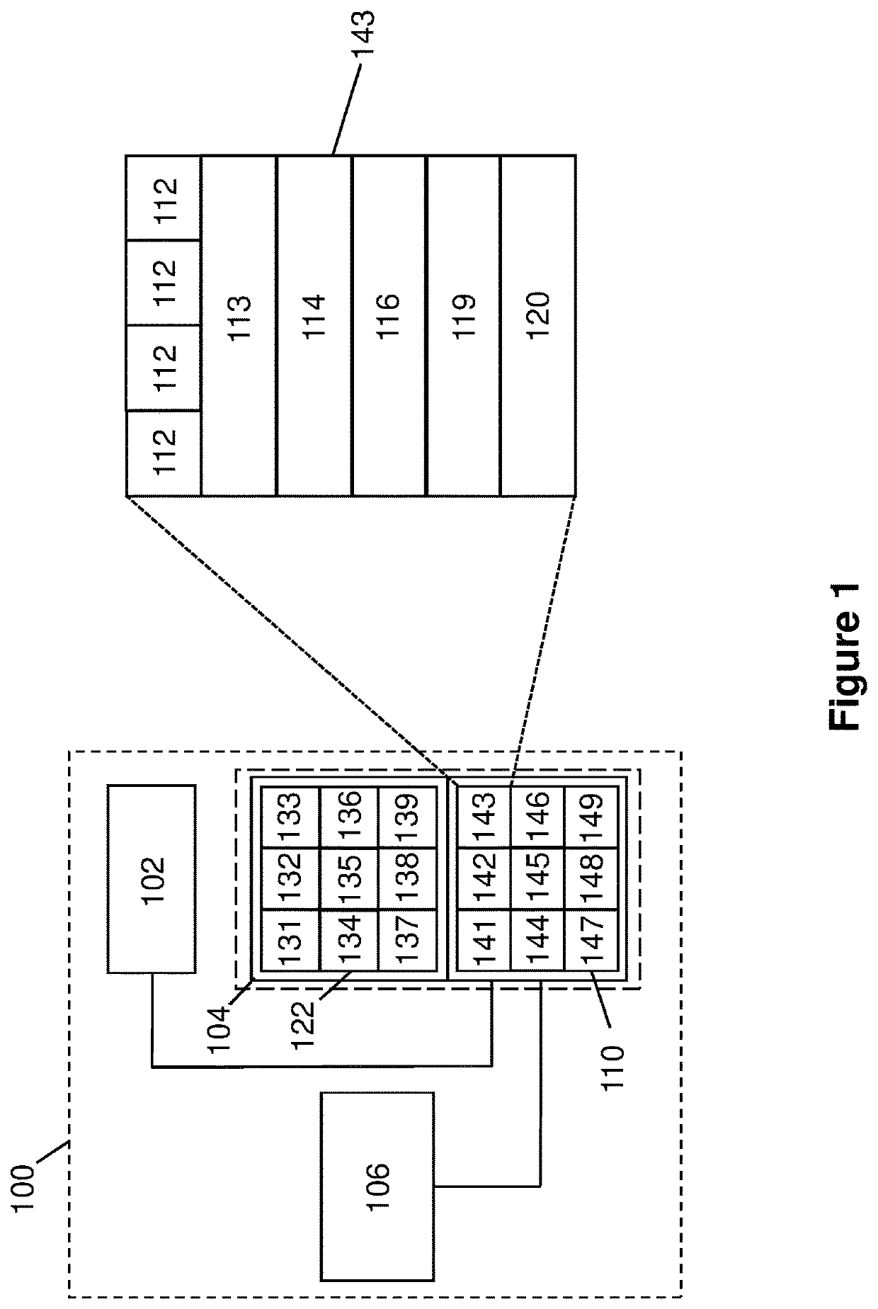
[0036]FIG. 1 schematically depicts a time of flight sensor system which may operate using a method according to an embodiment of the invention;

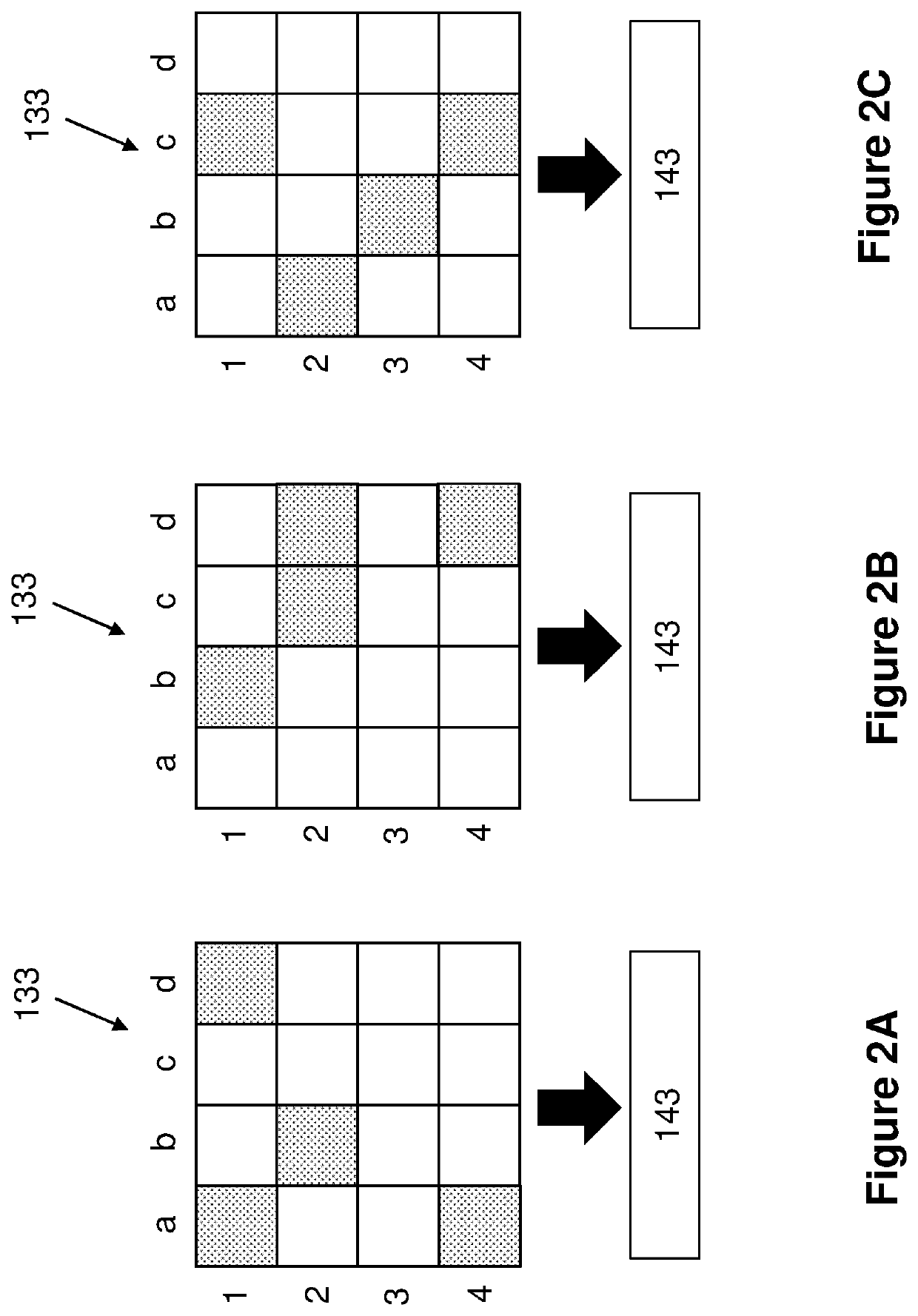
[0037]FIGS. 2A-2C schematically depicts a method of time of flight sensing according to an embodiment of the invention; and

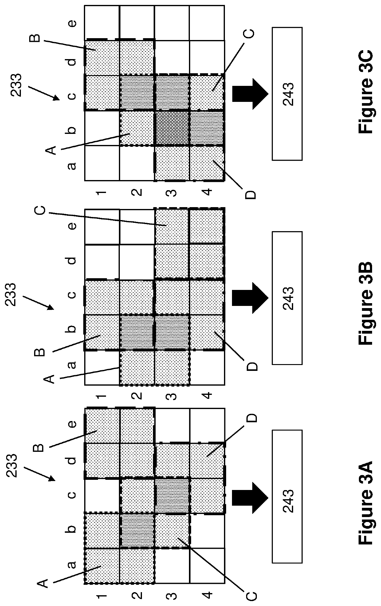
[0038]FIG. 3A-3C schematically depicts a method of time of flight sensing according to another embodiment of the invention.

DETAILED DESCRIPTION OF THE PREFERRED EMBODIMENTS

[0039]Generally speaking, the disclosure provides a method of time of flight sensing in which outputs are received from a subset of photodetectors for each output frame of a macropixel.

[0040]Some examples of the solution are given in the accompanying Figures.

[0041]FIG. 1 schematically depicts a time of flight sensor system 100 which may be operated in accordance with an embodiment of the invention. The time of f...


PUM


Abstract

A method of time of flight sensing, the method comprising using a source to emit pulses of radiation, and using an array of photodetectors arranged as a macropixel to detect radiation reflected from an object. During a sub-frame output from the macropixel, outputs from a subset of photodetectors of the macropixel are obtained, and during a subsequent sub-frame output from the macropixel, outputs from a different subset of photodetectors of the macropixel are obtained.

Description

TECHNICAL FIELD OF THE DISCLOSURE[0001]The disclosure relates to a method of time of flight sensing, and to a time of flight sensor module and a time of flight sensor system.BACKGROUND OF THE DISCLOSURE[0002]The present disclosure relates to a method of time of flight sensing. Time of flight sensing determines the distance of an object from a sensor using the known speed of light. In one example a pulse of light (e.g. at an infra-red wavelength) is emitted from a light source, and light reflected back towards the sensor from an object is detected. The source and the sensor may be located adjacent to one another (e.g. as part of the same integrated system). The distance between the sensor and the object is determined based upon the elapsed time between emission of the pulse of light and detection of the pulse of light by the sensor.[0003]The time of flight sensor may be an imaging array which comprises an array of photodetectors. The photodetectors may for example be single-photon av...

Claims


Application Information

Patent Timeline
IPC IPC(8): G01S7/4865G01S7/4863G01S7/481G01S17/894G01B11/22
CPCG01S7/4865G01S7/4863G01B11/22G01S17/894G01S7/4816G01S17/10G01S7/4811
Inventor STOPPA, DAVIDVAELLO PAÑOS, MIGUEL BRUNO
Owner AMS INT
Why Eureka
Try Eureka