Light emitting module

Pending Publication Date: 2022-07-28
NICHIA CORP
View PDF0 Cites 0 Cited by
  • Summary
  • Abstract
  • Description
  • Claims
  • Application Information

AI Technical Summary

Benefits of technology

The present invention provides a light-emitting module that can stop laser light when the converting member is damaged. This feature ensures the safety of the users and prevents accidents caused by the laser.

Problems solved by technology

In such light emitting modules, if the converting member is damaged due to an external impact, laser light may leak to the outside of the light-emitting module and may enter the human eye.
When the converting member is damaged, reliable termination of the lasing is required in such a stopping system.

Method used


Image

  • Light emitting module
  • Light emitting module
  • Light emitting module

Examples


Embodiment Construction

Structure

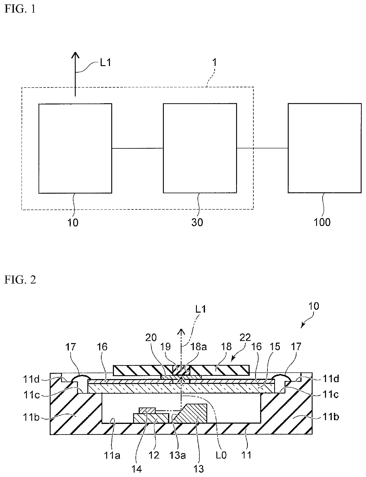
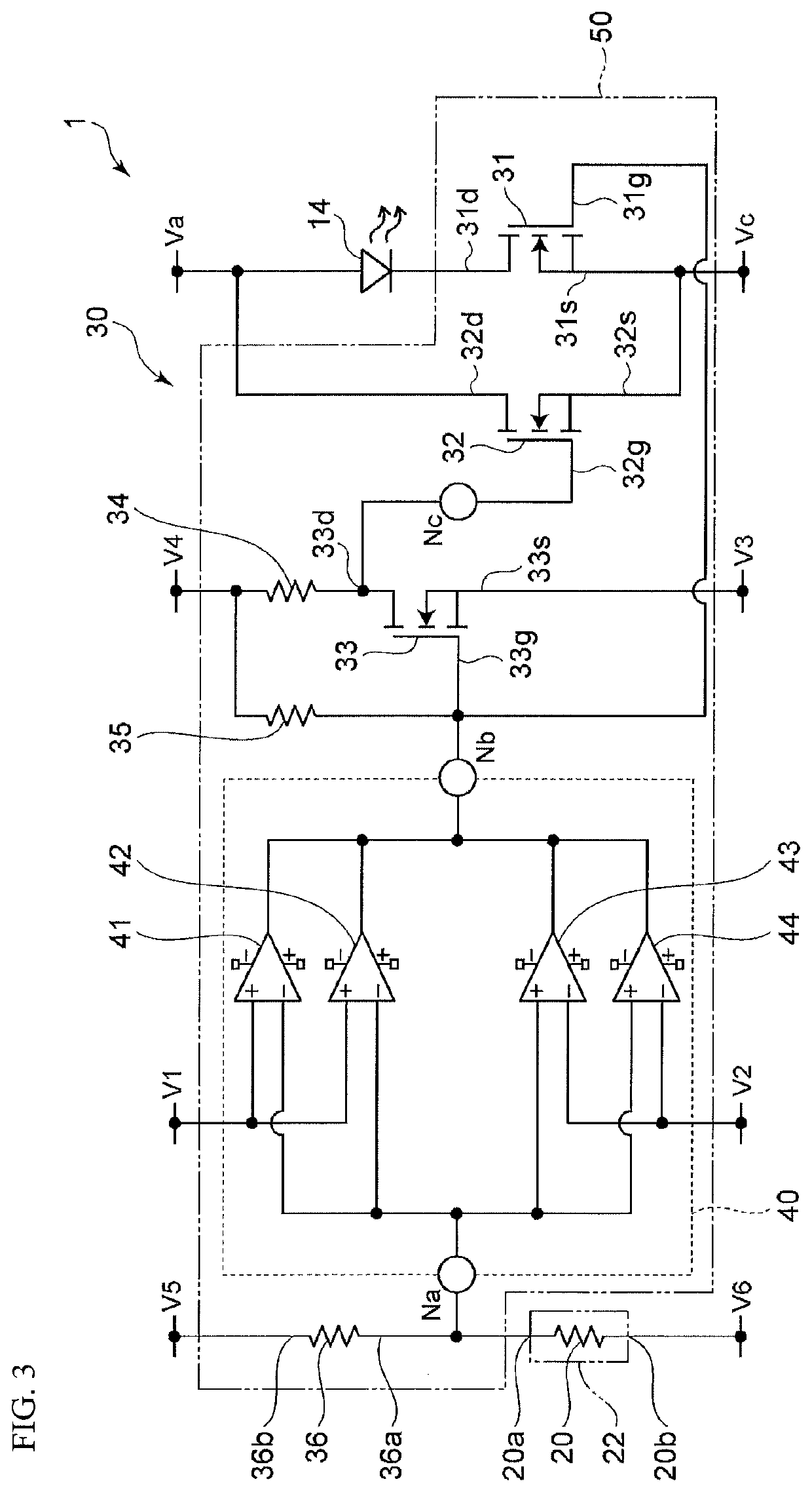
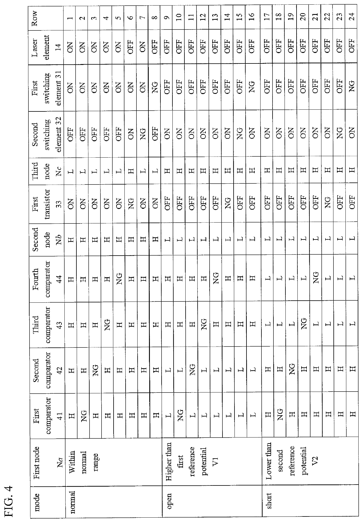
[0014]Next, one embodiment of the present disclosure will be described. FIG. 1 is a block diagram of a light-emitting module according to the present embodiment. FIG. 2 is a schematic cross-sectional view showing a light-emitting part of a light-emitting module according to the present embodiment. FIG. 3 is a circuit diagram showing a configuration of a light-emitting module according to the present embodiment.

[0015]As shown in FIG. 1, the light-emitting module 1 according to the present embodiment includes a light-emitting part 10 and a power supply part 30. The power supply part 30 is electrically connected to an external power source 100 to supply electric power to the light-emitting part 10. The light-emitting part 10 is caused to emit light L1 when the power is supplied from the power supply part 30.

Light-Emitting Part 10

[0016]As shown in FIG. 2, the light-emitting part 10 includes a casing 11. The casing 11 has a box-shape with an opening in an upper surface. For illu...


PUM


Abstract

A light-emitting module including: a laser element; a converting member; a sense wiring; an electric potential determining circuit configured to output a first value when an electric potential at a first end of the sense wiring is in a predetermined range, and to output a second value when the electric potential at the first end of the sense wiring is out of the predetermined range; a first switching element electrically connected in series to the laser element, the first switching element configured to become conductive when the output is the first value, and to become non-conductive when the output is the second value; and a second switching element electrically connected in parallel to a circuit comprising the laser element and the first switching element, the second switching element configured to become conductive when the output is the second value, and to become non-conductive when the output is the first value.

Description

CROSS-REFERENCE TO RELATED PATENT APPLICATION[0001]The present application claims priority under 35 U.S.C. § 119 to Japanese Patent Application No. 2021-010873, filed on Jan. 27, 2021. The contents of this application are incorporated herein by reference in their entirety.BACKGROUND OF THE INVENTIONField of the Invention[0002]The present disclosure relates to a light-emitting module.Discussion of the Background[0003]In recent years, light-emitting modules equipped with laser diodes (LD) have been developed for lighting devices and vehicular head lamps. In such light-emitting modules, a laser light emitted from an LD is irradiated to the converting member, the wavelength of the laser light is converted by the converting member, and is emitted to the outside as a light suitable for lighting. Laser light has relatively high coherence, but by passing through the converting member, light with lower coherence than that of the laser light is emitted to the outside.[0004]In such light emitt...

Claims


Application Information

Patent Timeline
IPC IPC(8): H01S5/068F21S41/16H01S5/02257
CPCH01S5/06825H01S5/02257F21S41/16F21S45/70H01S5/0087H01S5/02255H01S5/02208H01S5/042
Inventor SUZUKI, TAKUYA
Owner NICHIA CORP
Why Eureka
Try Eureka