
Method for Determining a Physical Parameter of a Pipe-Fluid System

a technology of pipe-fluid system and physical parameter, which is applied in the direction of instruments, specific gravity measurement, structural/machine measurement, etc., can solve the problems of tedious and time-consuming calibration of probes, and still quite costly to produce clamp-on devices adapted to pipe dimensions

Pending Publication Date: 2022-08-04
ABB (SCHWEIZ) AG
View PDF0 Cites 0 Cited by
  • Summary
  • Abstract
  • Description
  • Claims
  • Application Information

AI Technical Summary

Benefits of technology

The patent text describes a method to filter vibration data to improve accuracy and reliability. The filtering process can adjust the frequency range of the vibration data based on the data from the process and a model vibration spectrum. This helps to make the method more effective and reliable for analyzing vibration data related to the process.

Problems solved by technology

In many cases, it can be still rather costly to produce a clamp-on device adapted to the pipe dimensions and taking probes for calibration is also tedious and time consuming.

Method used


Image

  • Method for Determining a Physical Parameter of a Pipe-Fluid System
  • Method for Determining a Physical Parameter of a Pipe-Fluid System
  • Method for Determining a Physical Parameter of a Pipe-Fluid System

Examples


Embodiment Construction

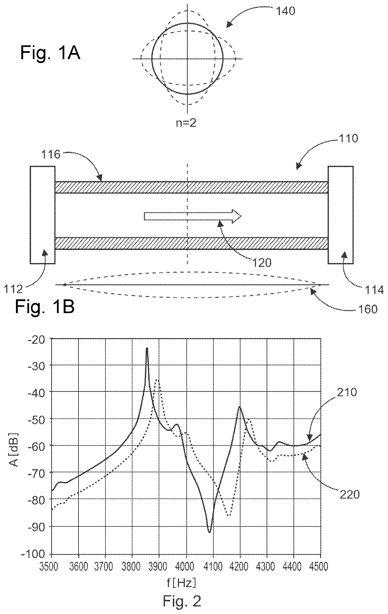
[0012]FIGS. 1A and 1B sketch schematically a section of a pipe 116, shown from an axial perspective at the top, as well as from a side perspective at the bottom, which is set up as a pipe-fluid system 110 comprising a vibration mode-confining element 112, 114 at both ends of the section of the pipe 116, wherein a fluid 120 is flowing inside of the pipe 116. Respective vibration modes 140, 160 are indicated as an example.

[0013]The modes are each characterized by the deformation in two planes. The circumferential deformations 140 and the longitudinal deformation 160. Any combination of these two deformation types is possible, being characterized by a combination of the characteristic numbers n and m, which are related to the number of vibrational nodes in the given plane. The examples refer to the combination n2m1, but other vibrational modes can be used to perform the determination.

[0014]FIG. 2 sketches schematically an example of a vibration frequency spectrum 210 where an amplitude...


PUM

PropertyMeasurementUnit
weightaaaaaaaaaa
Young's modulusaaaaaaaaaa
physical parameteraaaaaaaaaa

Abstract

A system and method for determining a physical parameter of a pipe-fluid system includes providing a mechanical vibration spectrum of the pipe-fluid system, which is generated by a mechanical excitation impacting an outer surface of the pipe-fluid system, providing characteristic data of a pipe of the pipe-fluid system, providing process-fluid data of the pipe-fluid system, determining a mechanical model vibration spectrum based on a provided theoretical model for the pipe-fluid system and the provided characteristic data of the pipe and the provided process-fluid data, and comparing the mechanical vibration spectrum and the model vibration spectrum for determining the physical parameter of the pipe-fluid system for determining the physical parameter of the pipe-fluid system.

Description

CROSS-REFERENCE TO RELATED APPLICATIONS[0001]This patent application claims priority to European patent application no. EP 21154214, filed on Jan. 29, 2021, which is incorporated herein by reference.BACKGROUND OF THE INVENTION[0002]Density sensing is a valuable measurement in industrial processes, delivering relevant information on product and process quality. Most available density sensing systems are invasive, requiring the insertion of a device with fluid contact into the process, partly even intrusive, needing a member protruding into the flow. This leads to long installation times and need for process interruption at installation, causing high cost in case of retrofit additionally to the already high cost of the devices, e.g. Coriolis or vibrating fork sensors. The openings in the process piping created by insertion of an additional device also involve safety hazards of potential leakage, which are met with additional effort in sealing and safety measures.[0003]For non-invasive...

Claims


Application Information

Patent Timeline
Patent Type & Authority Applications(United States)
IPC IPC(8): G01N9/24
CPCG01N9/24G06F30/23G06F2113/14G06F2113/08G06F2119/08G06F2119/14G01M5/0025G01M5/0066G01N29/222G01F1/84G01N29/02G01F1/666G01D21/02E21B49/08G01N29/024G01N11/167G01N29/46
Inventor SZASZ, PAULSOSALE, GURUPRASADBERNING, MATTHIASMIGUNOV, VADIM
Owner ABB (SCHWEIZ) AG
Learn More