
A method for mgp new energy grid-connected control

a new energy grid and control technology, applied in the field of grid control, can solve the problems of affecting the stability and reliability of the control system, the output power of new energy fluctuation and uncontrollable, and the output delay of the control system

Pending Publication Date: 2022-08-04
GUIZHOU POWER GRID CO LTD
View PDF0 Cites 0 Cited by
  • Summary
  • Abstract
  • Description
  • Claims
  • Application Information

AI Technical Summary

Benefits of technology

The present invention proposes a method for controlling the voltage and improving the stability of a power grid. This technology can make the grid more reliable and stable.

Problems solved by technology

The biggest difference is that the output power of new energy is fluctuant and uncontrollable.
On the one hand, the process of prediction will cause the output delay of the control system, on the other hand, if the prediction is not accurate, the stability and reliability of the control system will be affected.

Method used


Image

  • A method for mgp new energy grid-connected control
  • A method for mgp new energy grid-connected control
  • A method for mgp new energy grid-connected control

Examples


embodiment 1

[0032

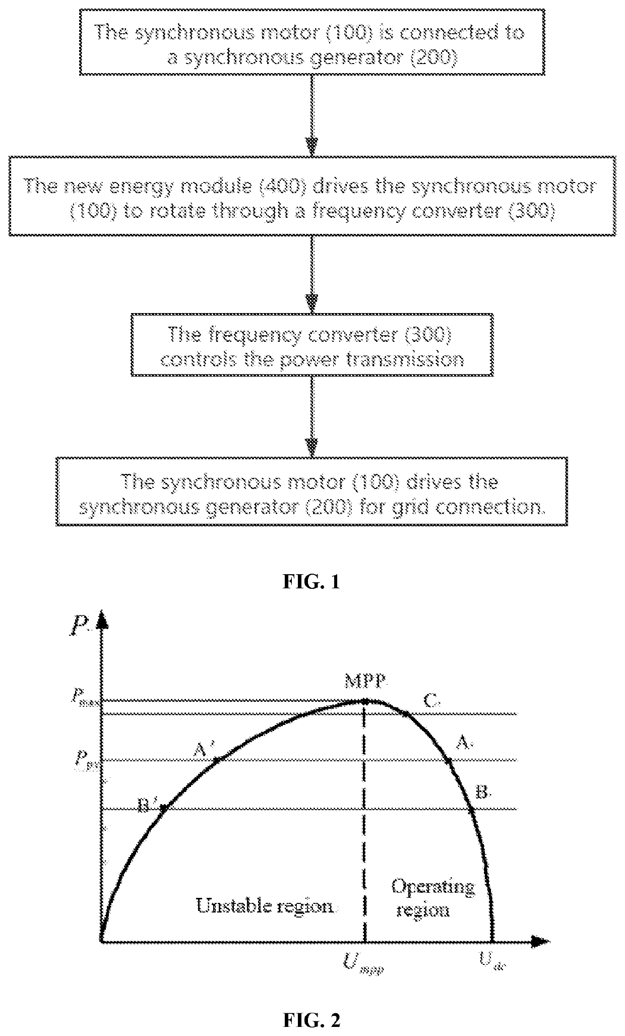
[0033]The FIG. 1 depicts the whole process of the MGP new energy grid-connected control method described in the embodiment of the invention, specifically including the following steps,

[0034]S1: the synchronous motor (100) is connected to a synchronous generator (200); S2: the new energy module (400) drives the synchronous motor (100) to rotate through the frequency converter (300).

[0035]Wherein, the frequency converter (300) also comprises the rectifier (301) and the inverter (302), and the DC capacitor (303) is arranged between the rectifier (301) and the inverter (302).

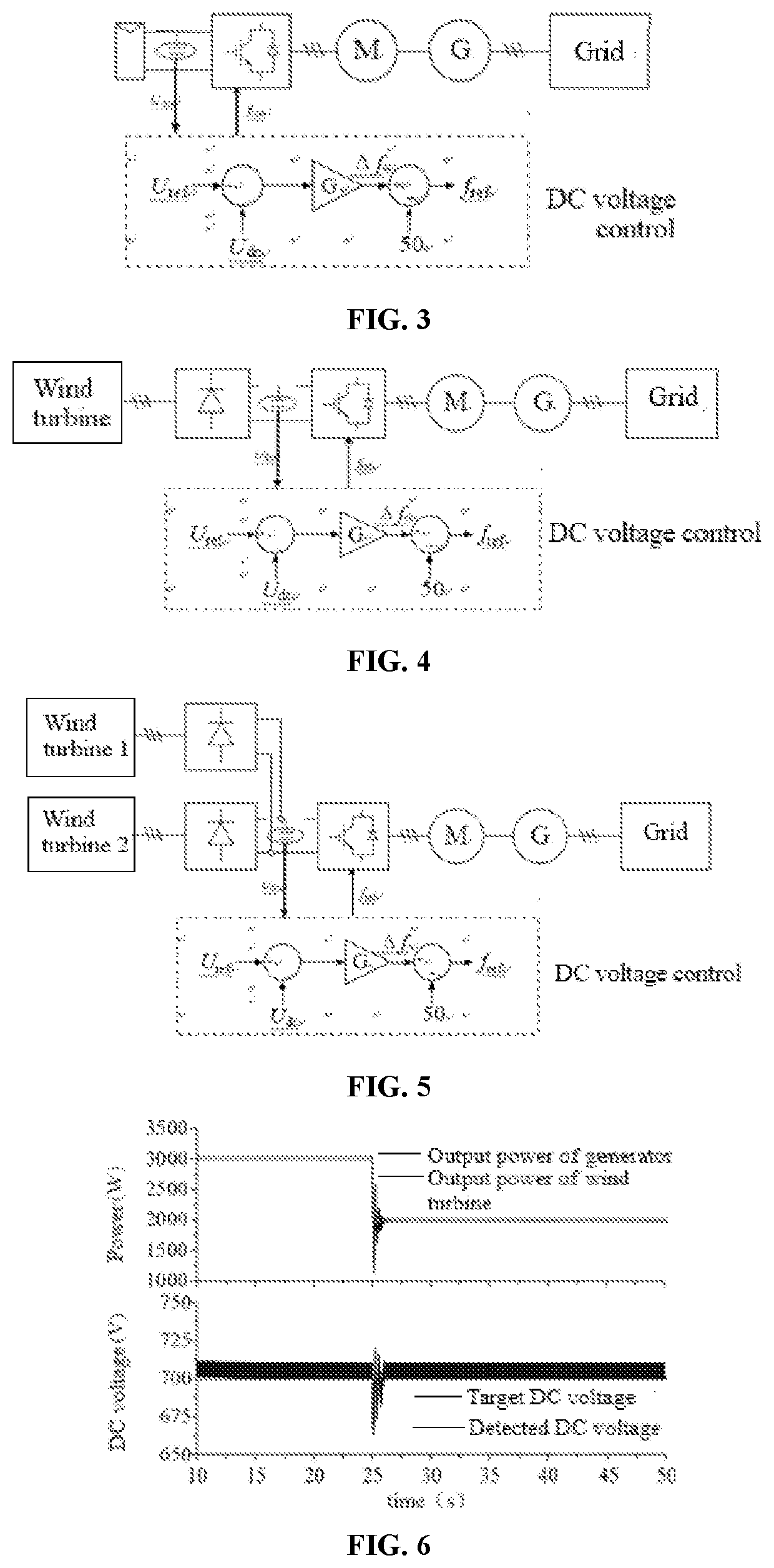
[0036]The new energy module (400) comprises P-V panels or wind turbines. When the new energy module (400) is connected to the grid through MGP, the whole grid-connected system consists of P-V panels or wind turbines, inverters, MGP and other units, and each unit has own operational characteristics. Therefore, the transmission control comprises the fusion of the operating characteristics of each serial module an...

embodiment 2

[0053

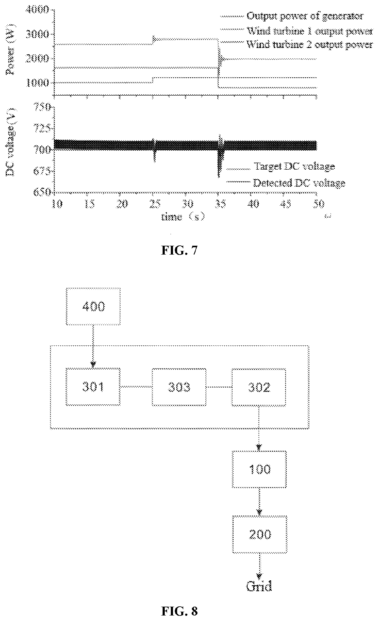
[0054]The FIG. 8 depicts the overall structure of the MGP new energy grid-connected control method described in the embodiment of the invention, the MGP new energy grid-connected control method can be realized based on the system. The system comprises the synchronous motor (100), the synchronous generator (200), the frequency converter (300) and the new energy module 400.

[0055]The synchronous motor (100) can be driven by the new energy module (400) to rotate.

[0056]The synchronous generator (200) can be connected to the grid under the drive of the synchronous motor (100); wherein, the synchronous motor (100) and the synchronous generator (200) can be connected by couplings.

[0057]The frequency converter (300) also comprises the rectifier (301), the inverter (302) and the DC capacitor (303), which can control the power transmission.

[0058]The new energy module (400) can drive the synchronous motor (100) through the frequency converter (300).

[0059]It should be recognized that, embod...


PUM


Abstract

The invention discloses a method for MGP new energy grid-connected control, wherein, the synchronous motor is connected to a synchronous generator; the new energy module drives the synchronous motor to rotate through a frequency converter; the frequency converter controls the power transmission; and the synchronous motor drives the synchronous generator for grid connection. The present invention has the beneficial effects that: the control method and system provided by the invention can improve the stability and reliability of the grid.

Description

FIELD OF THE INVENTION[0001]The invention relates to a technical field of grid control, in particular to a method and a system for MGP new energy grid-connected control.BACKGROUND OF THE INVENTION[0002]In recent years, new energy power generation has been developing continuously and received much attention. The characteristics of new energy generation are very different from those of traditional thermal power unit. The biggest difference is that the output power of new energy is fluctuant and uncontrollable. The traditional thermal power unit can be regarded as a power source that uses chemical energy to store energy and can adjust and control output power at any time, however, the new energy often needs the support of the power grid and delivers power to the grid randomly. Such characteristics make it necessary to predict the output power of new energy when MGP is connected to the grid based on power feedback control. On the one hand, the process of prediction will cause the output...

Claims


Application Information

Patent Timeline
IPC IPC(8): H02J3/38H02J3/42H02J3/46H02P9/10
CPCH02J3/381H02J3/42H02P2101/15H02P9/105H02J2300/28H02J3/46H02P11/06H02P2103/20H02J2300/24Y02E10/56
Inventor CHEN, JULONGZHAO, HAISENLIU, ZHENMINGSUN, BINXUE, YILI, QINGSHENGZHANG, YUTANG, XUEYONGZHAO, QINGMINGDENG, PU
Owner GUIZHOU POWER GRID CO LTD
Learn More