

Core part manufacturing method and core part manufacturing apparatus of rotary electric machine
- Summary
- Abstract
- Description
- Claims
- Application Information
AI Technical Summary
Benefits of technology
Problems solved by technology
Method used
Image

Examples
first embodiment
1. First Embodiment
[0032]Hereinafter, a core part manufacturing apparatus for a rotary electric machine according to a first embodiment of the present disclosure will be described with reference to FIGS. 1 to 5, FIGS. 6A and 6B, and FIGS. 7A and 7B.
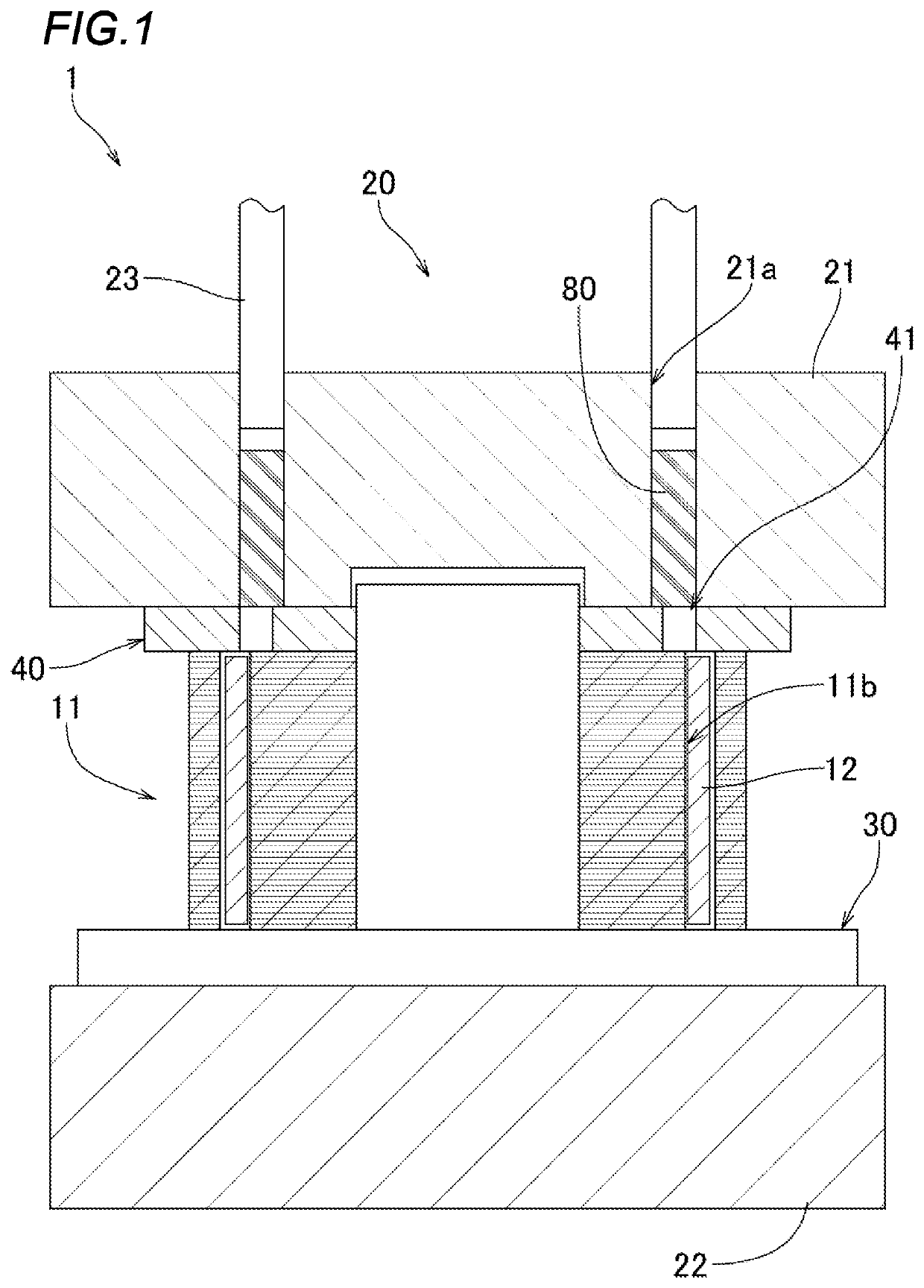
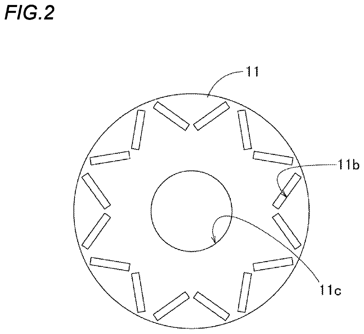
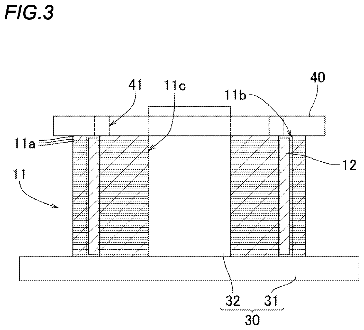
[0033]In each of the drawings, a core part manufacturing apparatus 1 according to the present embodiment is configured to manufacture a core part 10 forming a rotor of a rotary electric machine by filling a molten resin into a plurality of space portions to be filled with a resin in an iron core body 11 having the laminated structure and solidifying the molten resin. Specifically, the core part manufacturing apparatus 1 includes an injection mechanism portion 20 injecting the molten resin into the iron core body 11, a jig 30 supporting the iron core body 11 in a resin injection step performed by the injection mechanism portion 20 and before and after the resin injection step, and a plate-shaped auxiliary plate 40 attached to the iron core...
second embodiment
2. Second Embodiment
[0077]In the core part manufacturing apparatus 1 according to the first embodiment, resin injection is performed from an upper mold 21 side of the injection mechanism portion 20 to the iron core body 11, but the present disclosure is not limited thereto. As the second embodiment, as illustrated in FIGS. 8 to 10, and FIGS. 11A and 11B, the resin may also be injected from a lower mold 27 side of the injection mechanism portion 25.
[0078]In this case, the core part manufacturing apparatus 1 according to the present embodiment includes an injection mechanism portion 25, a jig 37, and an auxiliary plate 45 as in the first embodiment, and is different from the first embodiment in that the injection mechanism portion 25 is a mechanism that heats and melts the resin material 80 by the lower mold 27 and injects the molten resin into the iron core body 11 from the lower mold 27 side, and the jig 37 and the auxiliary plate 45 are configured in a shape corresponding to the re...
PUM
 Abstract
Description
Claims
Application Information