Thermal control device and methods utilizing temperature distribution modeling

a technology of temperature distribution and control device, applied in the direction of heat insulating device, heat measurement, instruments, etc., can solve the problems of increasing space and power requirements, lag and overlap problems frequently become worse, and not operating with rapid digital-like precision

Pending Publication Date: 2022-08-11
CEPHEID INC
View PDF0 Cites 1 Cited by
  • Summary
  • Abstract
  • Description
  • Claims
  • Application Information

AI Technical Summary

Problems solved by technology

Conventional systems typically use cooling devices (e.g., fans) that occupy a large amount of physical space and require significant power to provide a required amount of performance (i.e., a rapid temperature drop).
Fan-based cooling systems have issues with start-up lag time and shutdown overlap, that is, they will function after being shut off and thus do not operate with rapid digital-like precision.
Such lag and overlap issues frequently become worse with device age.
The answer thus far has been to incorporate more powerful fans with greater volumetric output rates, which also increase space and power requirements.
One price of this is a negative effect on portability of field testing systems, which can be used, for example, to rapidly detect viral/bacterial outbreaks in outlying areas.
Another problem is that this approach is less successful in higher temperature environments, such as may be found in tropical regions.
Because of the large thermal mass of the aluminum block, heating and cooling rates are limited to about 1° C./sec, so that a fifty-cycle PCR process may require two or more hours to complete.
In tropical climates, with elevated ambient temperatures the cooling rates can be adversely affected thus extending the time for thermal cycling from, for example, 2 hours to 6 hours.
W

Method used


Image

  • Thermal control device and methods utilizing temperature distribution modeling
  • Thermal control device and methods utilizing temperature distribution modeling
  • Thermal control device and methods utilizing temperature distribution modeling

Examples


Embodiment Construction

[0047]The present invention relates generally to systems, devices and methods for controlling thermal cycles in a chemical reaction, in particular, a thermal control device module adapted for use in controlling thermal cycling in a nucleic acid amplification reaction.

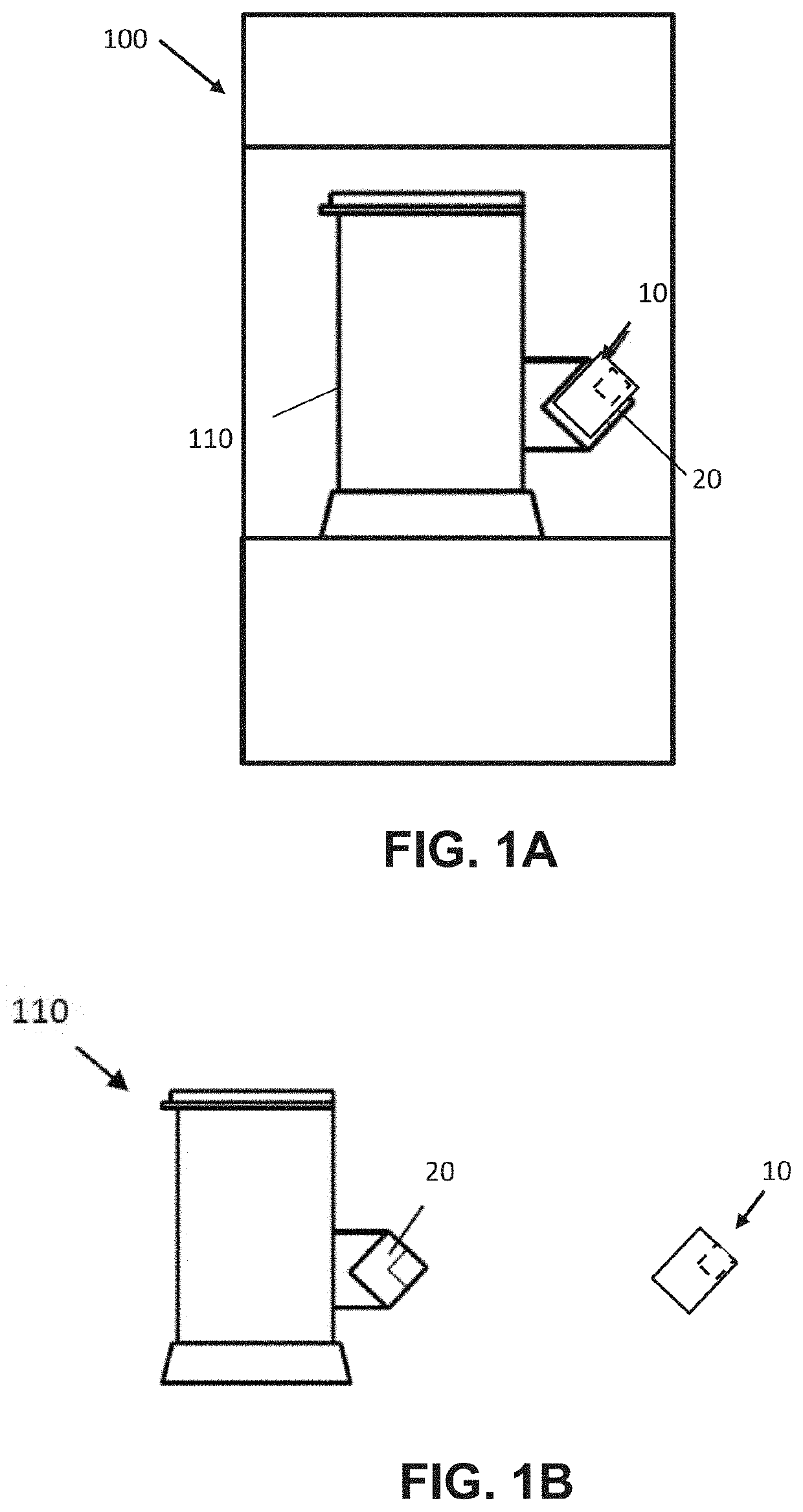
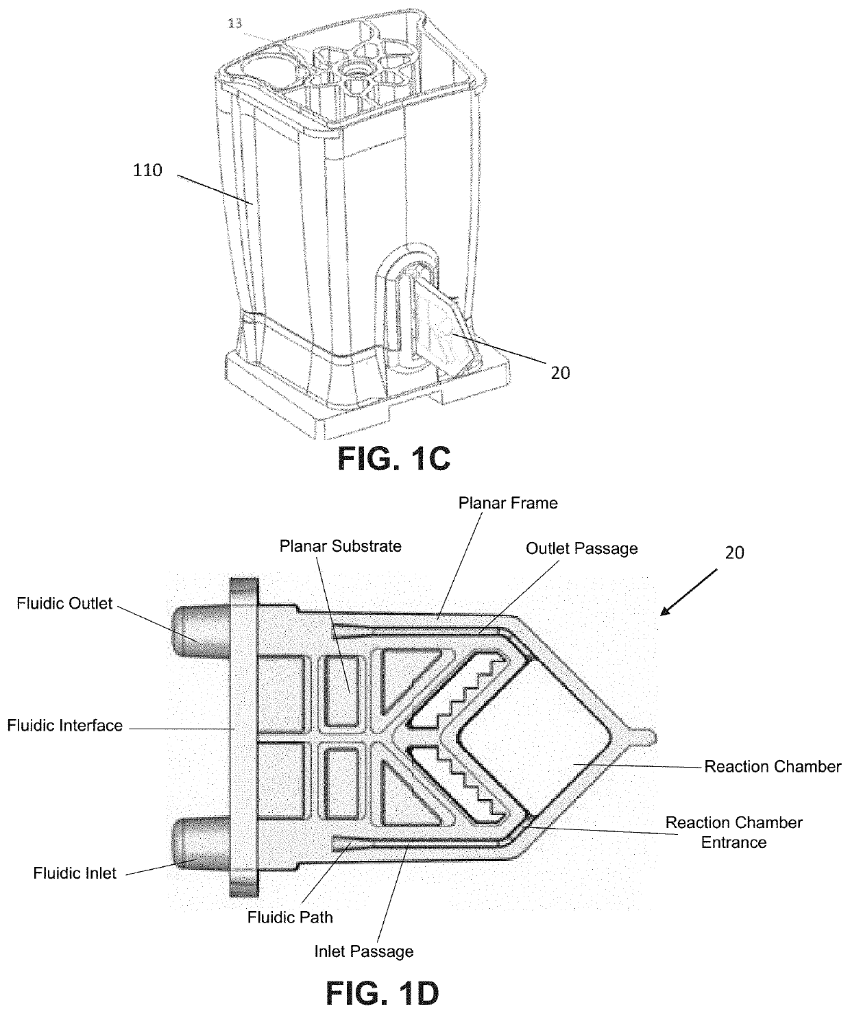
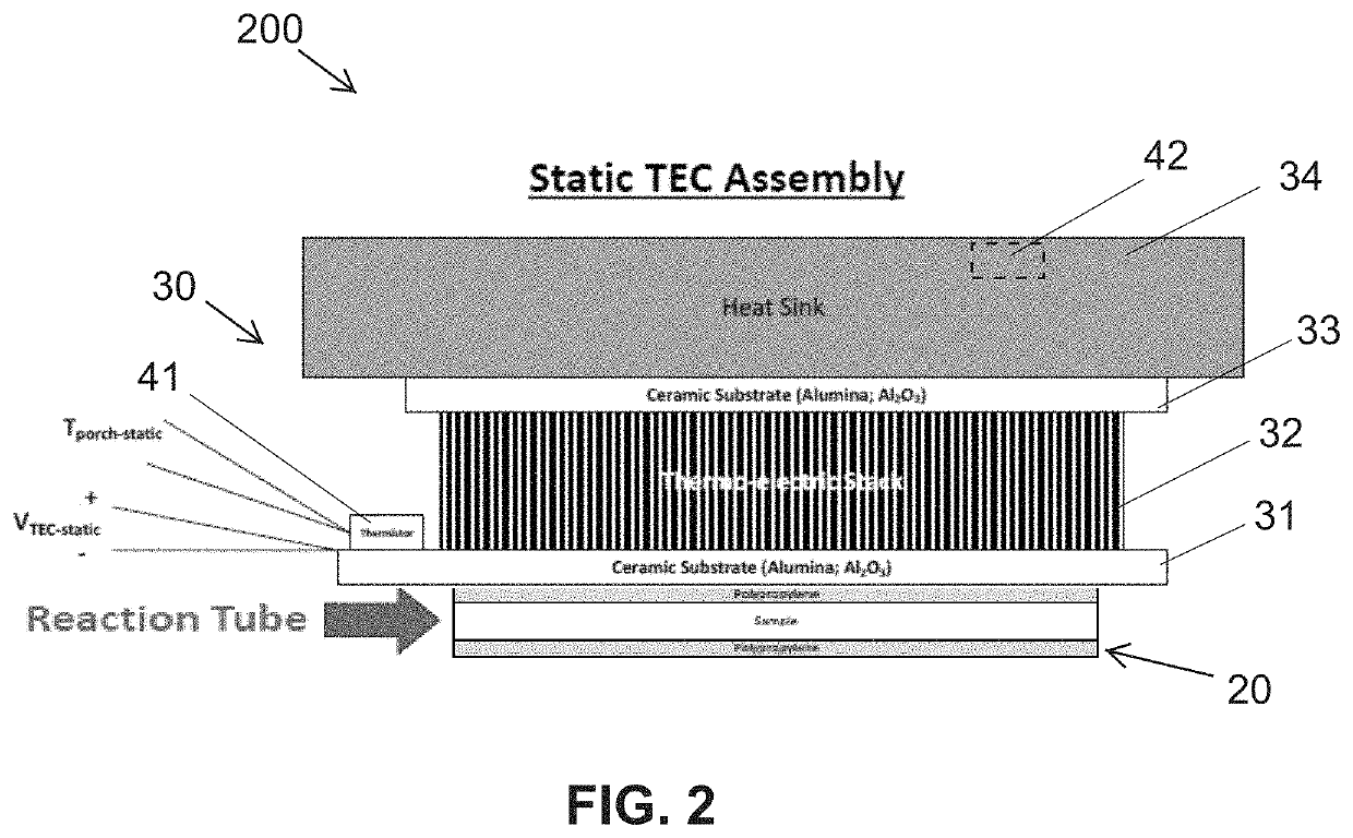
[0048]In one aspect, the invention provides a thermal control device that provides improved control and efficiency in thermal cycling, particularly thermal cycling for a polymerase chain reaction of a fluid sample in a reaction-vessel. Such devices can include one or more active elements (e.g. a TEC), each positioned in direct contact with or immediately adjacent the reaction-vessel so that a temperature of the active face of the TEC(s) can be used to control a temperature of the fluid sample within the reaction-vessel. Prior art approaches typically rely on the temperature of the TEC as corresponding to the temperature of the fluid sample and assume sufficient time for thermal conduction to equilibrate the temperature ...


PUM


Abstract

Thermal control devices and methods to provide improved control, speed and efficiency in temperature cycling are provided herein. Such thermal control device and methods can include one or more active elements, such a thermoelectric cooler device, that is controlled by an algorithm that regulates a temperature distribution of an adjacent reaction-vessel according to a temperature distribution command trajectory and estimated reaction-vessel temperature distribution. Some embodiments include two active elements that are bilaterally applied to opposing sides of the reaction-vessel. In some embodiments, the estimated reaction-vessel temperature is determined based on a state of power electronics of the element and a temperature output of one or more sensors of a portion of the element and/or an ambient environment of the reaction-vessel. Methods of calibration of such systems utilizing a thermal calibrator as a proxy for the reaction-vessel are also provided herein.

Description

CROSS-REFERENCES TO RELATED APPLICATIONS[0001]This application is a Non-Provisional of and claims the benefit of priority of U.S. Provisional Application No. 63 / 136,968 filed on Jan. 13, 2021, the entire contents of which are incorporated herein by reference.STATEMENT AS TO RIGHTS TO INVENTIONS MADE UNDER FEDERALLY SPONSORED RESEARCH AND DEVELOPMENT[0002]This invention was made with U.S. Government support under Agreement No. W15QKN-16-9-1002 awarded by the ACC-NJ to the MCDC. The Government has certain rights in the invention.BACKGROUND OF THE INVENTION[0003]The present invention relates generally to thermal control devices, more particularly to a device, system and methods for controlling temperature, particularly thermal cycling in a nucleic acid analysis.[0004]This application is generally related to: U.S. Pat. No. 10,544,966 entitled “Thermal Control Device and Methods of Use” issued on Jan. 28, 2020; U.S. patent application Ser. No. 13 / 843,739 entitled “Honeycomb tube,” filed ...

Claims


Application Information

Patent Timeline
IPC IPC(8): G05D23/19F25B21/02G01K1/02G01K13/024G01N1/42G01N1/44B01L7/00B01L1/02
CPCG05D23/1931F25B21/02G01K1/026G01K13/024G01N1/42B01L2300/0681B01L7/52B01L1/025B01L2300/1822B01L2300/0663B01L2300/1894G01N1/44G05D23/1919G01N2035/00346B01L9/06B01L7/04B01L2200/148B01L2200/147
Inventor LEE, MARISSAKOAY, JESSICAROHRS, CHARLESSOLIS, EARLPICCINI, MATTHEWCASLER, JR., RICHARD J.
Owner CEPHEID INC
Why Eureka
Try Eureka