Vapor deposition source, vapor deposition apparatus, and film-forming method

a technology of vapor deposition source and vapor deposition apparatus, which is applied in the direction of vacuum evaporation coating, chemical vapor deposition coating, coating, etc., can solve the problems of inferior goods and achieve the effect of large light-emitting amoun

Inactive Publication Date: 2010-01-21
ULVAC INC
View PDF7 Cites 31 Cited by
  • Summary
  • Abstract
  • Description
  • Claims
  • Application Information

AI Technical Summary

Benefits of technology

[0028]The vapor deposition source of the present invention can be operated for a long time, and since a vapor deposition material is not exposed to a high temperature for a long time, the vapor deposition material does not decompose or degenerate. A thin film having the same chemical composition as that of the vapor deposition material can be formed. The use of the vapor deposition source of the present invention for forming an organic layer of organic EL apparatuses enables organic EL apparatuses having a large light-emitting amount to be manufactured. Since the vapor deposition material does not run short during film formation, the goods that are generated are not inferior. Thin films having uniform thickness distribution are formed.

Problems solved by technology

Further, when an evaporation rate of the organic vapor deposition material 200 increases due to, for example, a problem with a heater, or when the transfer speed of the substrate 205 becomes slow, the organic vapor deposition material 200 runs short while forming a film for the substrate 205, thereby resulting in inferior goods.

Method used


Image

  • Vapor deposition source, vapor deposition apparatus, and film-forming method
  • Vapor deposition source, vapor deposition apparatus, and film-forming method
  • Vapor deposition source, vapor deposition apparatus, and film-forming method

Examples


Embodiment Construction

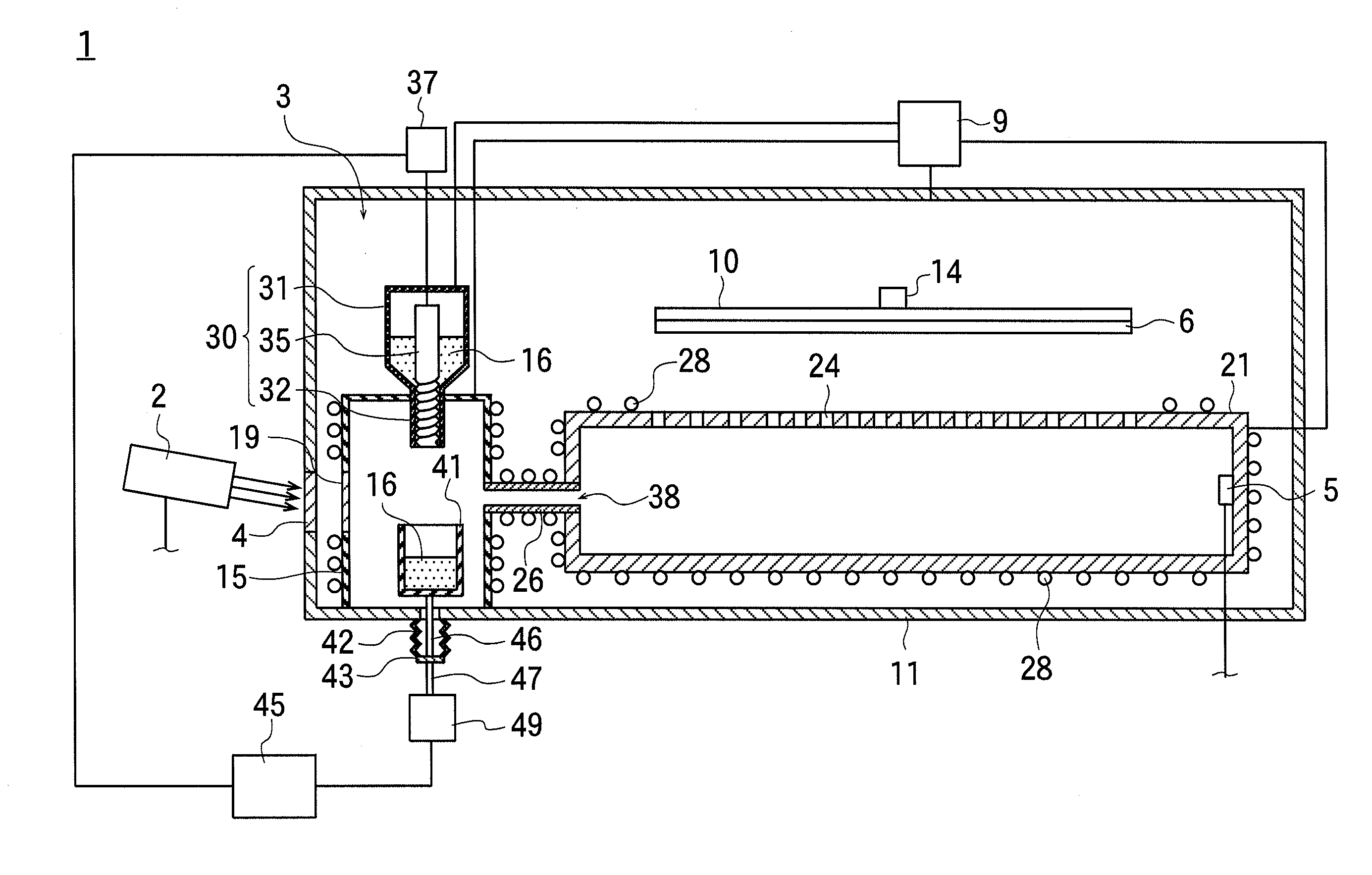
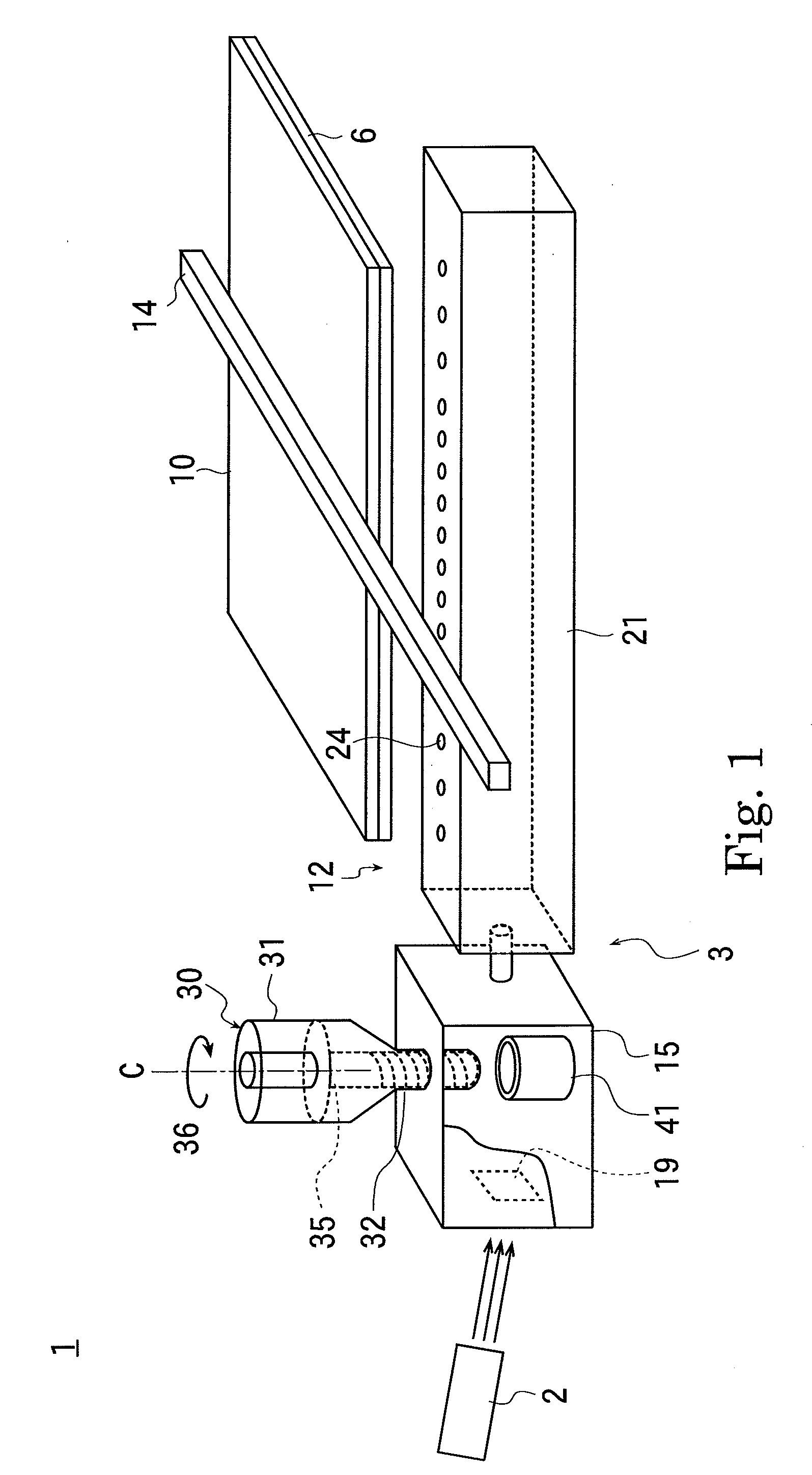
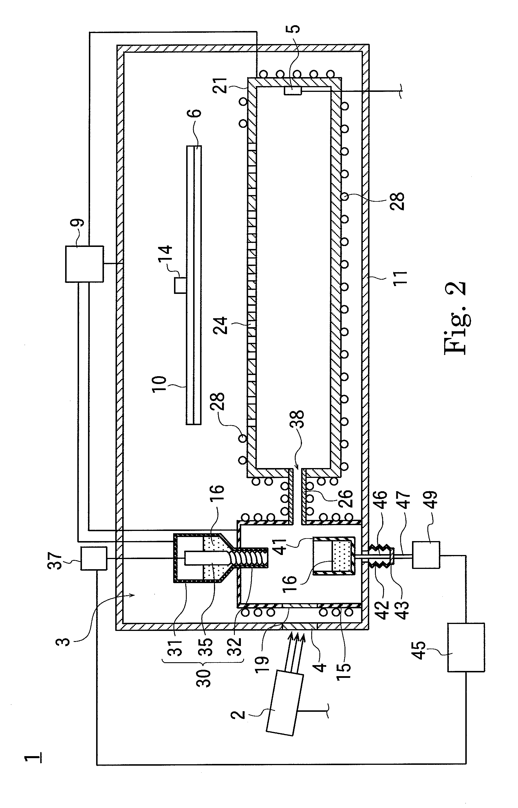
[0033]In the perspective view shown in FIG. 1 and the schematic cross-sectional view shown in FIG. 2, reference numeral 1 denotes a vapor deposition apparatus that is an embodiment of the present invention and also the first example. The vapor deposition apparatus 1 has a vacuum chamber 11 and a vapor deposition source 3 (in FIG. 1, the vacuum chamber 11 is omitted).

[0034]An evacuation system 9 is connected to the vacuum chamber 11; and by operating the evacuation system 9, the inside of the vacuum chamber 11 is evacuated.

[0035]The vapor deposition source 3 has a vapor deposition container 21, an evaporation chamber 15, a feed device 30, a tray 41, a mass meter 49, and a controller 45. The vapor deposition container 21 is disposed inside the vacuum chamber 11.

[0036]The vapor deposition container 21 has one or a plurality of ejection ports 24. As discussed later, the vapor deposition container 21 is constituted such that, when the vapor deposition material 16 fed from the feed device...


PUM

PropertyMeasurementUnit
inner diameteraaaaaaaaaa
wavelengthaaaaaaaaaa
massaaaaaaaaaa

Abstract

A vapor deposition apparatus capable of forming an organic thin film having a good film quality is provided. In the vapor deposition apparatus of the present invention, a tray is disposed in an evaporation chamber, and a feed device feeds a vapor deposition material onto the tray. The tray is placed on a mass meter, which measures the mass of the vapor deposition material disposed on the tray, and a controller compares the measured value with a reference value in order to make the feed device feed the vapor deposition material in a necessary amount. Since the vapor deposition material is replenished when needed, the vapor deposition material does not run short during the film formation, or a large amount of the vapor deposition material is not heated for a long time. Thus, the vapor deposition material does not change in quality.

Description

[0001]This is a Continuation of International Application No. PCT / JP2008 / 054876 filed on Mar. 17, 2008, which claims priority of Japan Patent Document No. 2007-078252 filed on Mar. 26, 2007. The entire disclosure of the prior application is incorporated by reference herein in its entirety.BACKGROUND[0002]The present invention generally relates to a technical field of an organic thin film, and more particularly, to a technology for manufacturing an organic thin film having good quality.[0003]Organic EL elements are the types of display elements that attract the highest attention recently, and have such excellent properties as high brightness and quick response speed. In organic EL elements, light-emitting areas that emit three different colors of red, green and blue are disposed on a glass substrate. The light-emitting area is formed by stacking an anode electrode film, a hole injection layer, a hole transport layer, a light-emitting layer, an electron transport layer, an electron in...

Claims


Application Information

Patent Timeline
Patent Type & Authority Applications(United States)
IPC IPC(8): C23C16/52C23C16/00
CPCC23C14/12C23C14/246C23C14/243C23C14/24
Inventor NEGISHI, TOSHIO
Owner ULVAC INC
Why Eureka
Try Eureka