Supercharge Your Innovation With Domain-Expert AI Agents!

Bioabsorbable flow diverting scaffold and methods for its use

Pending Publication Date: 2022-08-18
FLUID BIOMED INC
View PDF0 Cites 0 Cited by
  • Summary
  • Abstract
  • Description
  • Claims
  • Application Information

AI Technical Summary

Benefits of technology

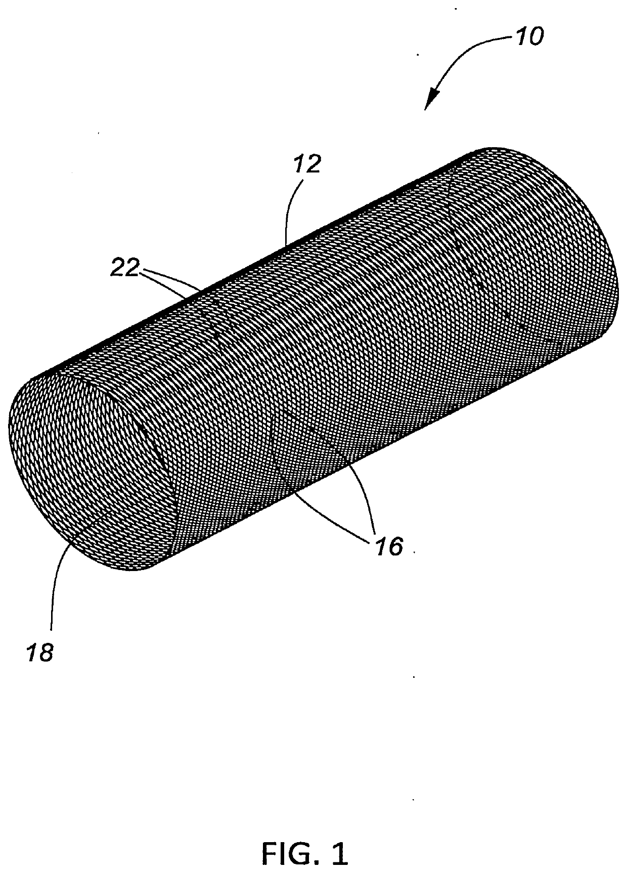
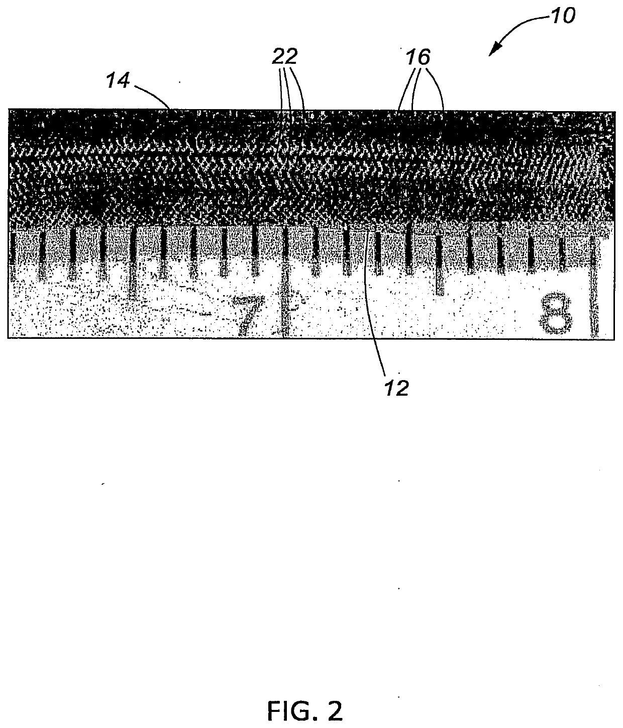
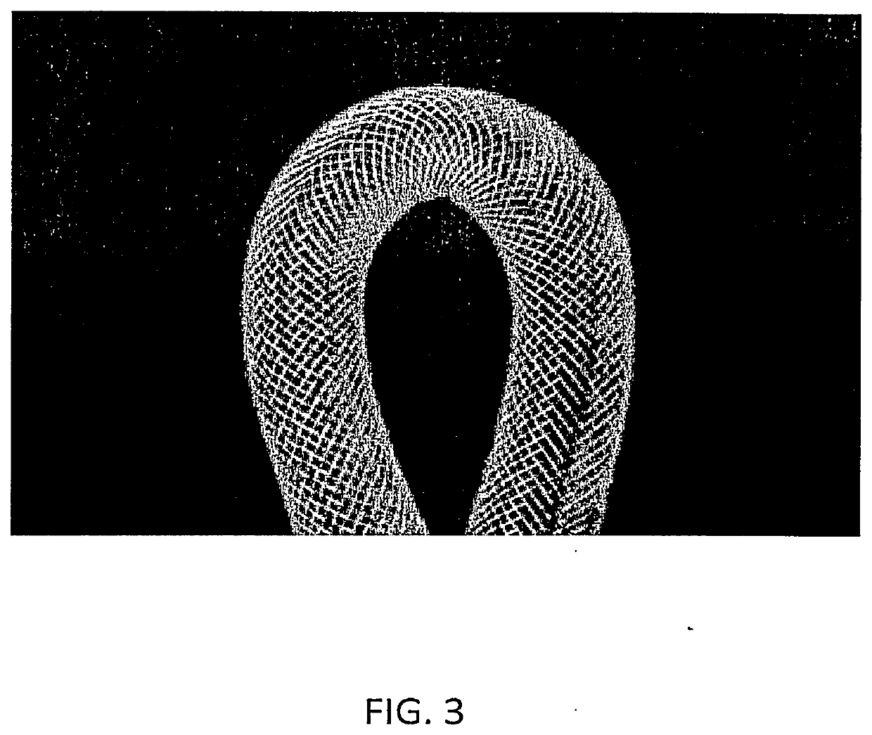
The present invention relates to a device for positioning in a body lumen, such as a blood vessel or ureter, for the treatment of blockages or other issues. The device comprises a resiliently deformable tubular body made of interwoven bioabsorbable polymeric fibers. The device has a porosity in the range of about 5% to about 80% when in an expanded formation. The device can be expanded to a diameter of about 4 mm or more. The bioabsorbable polymeric fibers have a diameter of about 30 μm or more. The device can be used with a visualization aid, such as radio-opaque material. The device also has means for facilitating and maintaining radial and axial expansion in the body lumen.

Problems solved by technology

Aneurysms have thin, weak walls and are thus at risk of rupturing.
As they are permanent and cannot be removed, they present various drawbacks, including risk of thrombosis that requires patients to remain anti-platelet medications long-term, risk of hyperplasia, prevention of vascular lumen remodeling or expansion, and occlusion of the blood vessel.
Metal scaffolds are also present disadvantages in the context of CT and MRI imaging post-implantation as the signal they reflect tends to be too bright.

Method used


Image

  • Bioabsorbable flow diverting scaffold and methods for its use
  • Bioabsorbable flow diverting scaffold and methods for its use
  • Bioabsorbable flow diverting scaffold and methods for its use

Examples


example 1

[0156]Referring to FIG. 4, a device was made constructed with 48 bioabsorbable polymeric fibers of poly-L-lactic acid with a molecular weight of 30,000 g / mol and a diameter of 50 μm

example 2

[0157]Referring to FIG. 7, a device was made constructed with 44 bioabsorbable polymeric fibers of poly-L-lactic acid with a molecular weight of 30,000 g / mol and a diameter of 50 μm interwoven with four radio-opaque fibers of tantalum-coated nitinol. The device was tested in animal blood vessels, i.e. rabbit aortas, and was able to keep important vascular side branches open without occluding any of the blood vessels.

[0158]FIGS. 11A and 11B are time lapse photos of an angiogram of an aneurysm during early arterial and early venous phase prior to implantation of the device. The rapid washout of signal from the aneurysm shown in FIG. 11B is indicative of fluid flow into the aneurysm. In contrast, FIG. 11C shows early venous phase after implantation of the device, wherein signal is retained in the aneurysm. This indicates that blood is no longer flowing freely into the aneurysm and that the device is successfully diverting flow from the aneurysm.

[0159]Referring to FIGS. 12A and 12B, rab...

example 3

[0169]Referring to FIG. 8A a device was made constructed with 46 bioabsorbable polymeric fibers of poly-L-lactic acid with a molecular weight of 30,000 g / mol and a diameter of 50 μm interwoven with two radio-opaque fibers of tantalum-coated nitinol. The device was tested in animal blood vessels and was able to keep important vascular side branches open without occluding any of the blood vessels.

[0170]Referring now to FIGS. 18A to 18F, methods for delivering the flow diverting stents of the present invention to a cerebral aneurysm A will be described. While the specific description relates to stent delivery at an aneurysm A having a neck N located at a vascular bifurcation having a main lumen ML, a first branch lumen, and a second branch lumen BL2, the methods described will work as well with wide neck and other sidewall aneurysms. As shown in FIG. 18A, the aneurysm A is located at the base or “groin” of the bifurcation and separates the openings into each of the branch vessels BL1 a...


PUM

PropertyMeasurementUnit
Pressureaaaaaaaaaa
Pressureaaaaaaaaaa
Pressureaaaaaaaaaa

Abstract

This disclosure relates to scaffolds made of a braid of bioabsorbable polymeric fibers for implantation within a lumen of a mammalian body and, in particular, to such scaffolds that are configured to divert blood flow from a pathology associated with a blood vessel.

Description

CROSS-REFERENCE TO RELATED APPLICATION[0001]The present application is a continuation-in-part of U.S. application Ser. No. 16 / 810,679 (Attorney Docket No. 62197-703.301), filed on Mar. 5, 2020, which is a continuation of PCT / CA2019 / 050304 (Attorney Docket No. 62197-703.601), filed on Mar. 12, 2019, which claims the benefit of U.S. provisional application 62 / 641,891 (Attorney Docket No. 62197-703.101), filed on Mar. 12, 2018, the full disclosures of which are incorporated herein by reference.BACKGROUND OF THE INVENTION1. Field of the Invention[0002]This disclosure relates to scaffolds made of a braid of bioabsorbable polymeric fibers for implantation within a lumen of a mammalian body. Particular aspects of this disclosure relate scaffolds made from such braids that are configured to divert blood flow from a pathology associated with a blood vessel.2. Description of the Background Art[0003]There is an abundance of medical devices that are known in the art, which are implanted into bl...

Claims


Application Information

Patent Timeline
IPC IPC(8): A61L27/58A61L27/56A61L27/06A61L27/04A61L27/18A61F2/07A61F2/90
CPCA61L27/58A61L27/56A61L27/06A61L27/045A61L27/18A61F2310/00023A61F2/90A61F2210/0004A61F2250/0098A61F2310/00029A61F2/07A61F2250/0031A61F2002/823A61L31/148A61L31/18A61L31/146A61L31/022A61L31/06C08L67/04
Inventor MITHA, ALIM P.WONG, JOHN H.
Owner FLUID BIOMED INC
Features
  • R&D
  • Intellectual Property
  • Life Sciences
  • Materials
  • Tech Scout
  • Unparalleled Data Quality
  • Higher Quality Content
  • 60% Fewer Hallucinations
Learn More