
Solid end mill

a technology of solid end mills and end mills, which is applied in the direction of metal-working equipment, milling equipment, manufacturing tools, etc., can solve the problems of insufficient cutting performance and chip evacuation, and the complexity of grinding operations

Pending Publication Date: 2022-08-25
SANDVIK COROMANT
View PDF0 Cites 0 Cited by
  • Summary
  • Abstract
  • Description
  • Claims
  • Application Information

AI Technical Summary

Benefits of technology

The invention is a solid end mill with improved cutting performance and tool life. It is achieved by designing the peripheral cutting edge with a linear and constant axial inclination angle of 5-15 degrees and positive radial rake angles along its entire extension. This allows for a more stable and efficient grinding operation, resulting in improved cutting performance and reduced strains on the cutting edge. The end mill also has a more stable cutting action and better chip evacuation compared to traditional non-inclined flutes. Additionally, it provides a more stable and efficient cutting action even with a smaller number of flutes.

Problems solved by technology

An axial inclination angle below 5° approaches the known tulip end mill having the non-inclined flutes, whereby for instance the cutting performance and chip evacuation becomes inadequate.
However, an axial inclination angle above 15°, given the axial extension on the peripheral cutting edges of the tulip / onion end mill, may lead to peripheral cutting edges that extend in a helix around the circumference of the solid end mill, whereby the grinding operation becomes more complex including the undesired variations on the radial rake angles.

Method used


Image

  • Solid end mill
  • Solid end mill
  • Solid end mill

Examples


Embodiment Construction

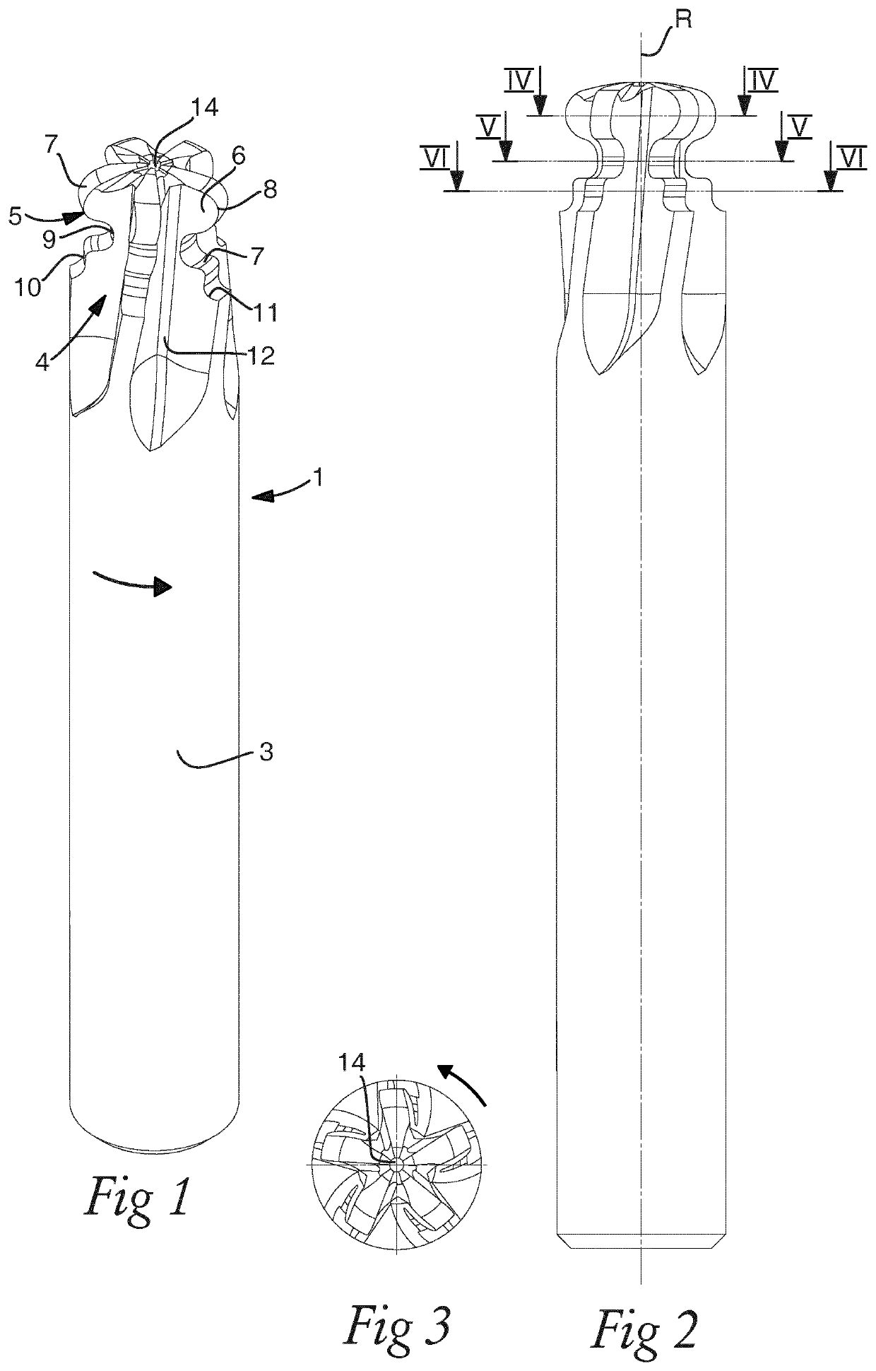
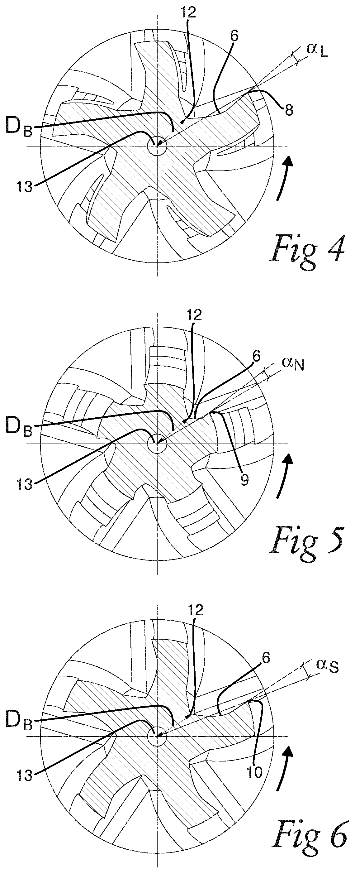
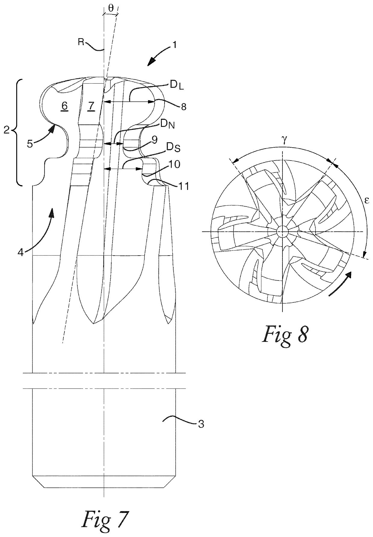
[0027]FIGS. 1-8 discloses a solid end mill according to an embodiment of the present invention. The solid end mill 1 is rotatable around a central rotational axis R, wherein the solid end mill has a cutting portion 2 and a shank portion 3. The cutting portion 2 includes a plurality flutes 4 with peripheral cutting edges 5 formed between associated rake surfaces 6 and clearance surfaces 7. Each peripheral cutting edge 5, in a view perpendicular to the central rotational axis and toward the rake surface 6, is forming a single convexly curved lobe cutting edge portion 8 disposed along an axial front part of the cutting portion 2. A single neck cutting edge portion 9 is connected to the convexly curved lobe cutting edge portion 8, wherein the neck cutting edge portion 9 extends at a smaller radial distance DN to the central rotational axis R compared to the convexly curved lobe cutting edge portion 8 and is disposed along an axial intermediate part of the cutting portion 2. A shoulder c...


PUM


Abstract

A solid end mill is rotatable around a central rotational axis and includes a cutting portion having a plurality flutes with peripheral cutting edges formed between associated rake surfaces and clearance surfaces. The peripheral cutting edge forms a convexly curved lobe cutting edge portion disposed along an axial front part of the cutting portion. A neck cutting edge portion is connected to the lobe cutting edge portion and is disposed along an axial intermediate part of the cutting portion. A shoulder cutting edge portion is connected to the neck cutting edge portion and is disposed along an axial rear part of the cutting portion. The peripheral cutting edge extends at a linear and constant axial inclination angle θ within the range 5°≤θ≤15°. The rake surface forms positive radial rake angles αL,N,S along the entire extension of the peripheral cutting edge.

Description

TECHNICAL FIELD OF THE INVENTION[0001]The present invention relates to a solid end mill being rotatable around a central rotational axis, wherein the solid end mill has a cutting portion and a shank portion. The cutting portion includes a plurality of flutes with peripheral cutting edges formed between associated rake surfaces and clearance surfaces. Each peripheral cutting edge, in a view perpendicular to the central rotational axis and toward the rake surface of the solid end mill, is forming a single convexly curved lobe cutting edge portion disposed along an axial front part of the cutting portion and a single neck cutting edge portion connected to the lobe cutting edge portion. The neck cutting edge portion extends at a smaller radial distance to the central rotational axis compared to the convexly curved lobe cutting edge portion and is disposed along an axial intermediate part of the cutting portion. The peripheral cutting edge is further forming a shoulder cutting edge porti...

Claims


Application Information

Patent Timeline
Patent Type & Authority Applications(United States)
IPC IPC(8): B23C5/10
CPCB23C5/10B23C5/14
Inventor ROYER, RAPHAEL
Owner SANDVIK COROMANT
Learn More