Method for preparing liquid medium composition, and preparation device and kit therefor
a technology of liquid medium and production method, which is applied in the direction of packaging foodstuffs, pharmaceutical containers, packaged goods types, etc., can solve the problems of inability to easily contact the second center part of the container, difficulty in individual use of such special stirring apparatus for each small capacity container, and inability to achieve the preferred flow rate. , to achieve the effect of reducing the speed of the two liquids at the junction where the two liquids meet, and reducing the length of the string of structures
- Summary
- Abstract
- Description
- Claims
- Application Information
AI Technical Summary
Benefits of technology
Problems solved by technology
Method used
Image
Examples
experimental example 1
the Production Device and Production Method of the Present Invention
[0162]One embodiment of the production device of the present invention was produced, the production method of the present invention was carried out using same, and the results of the test observing the dispersion state of the structure in the obtained medium composition are shown in the following. As a Comparative Example, the test results when the flow rate of the injection of the first liquid was decreased are shown.
[0163]In Examples 1-9 and Comparative Examples 1-16, a particular compound was deacylated gellan gum, the first liquid was a deacylated gellan gum solution, and a liquid medium containing calcium ion and magnesium ion as a linking substance to link the deacylated gellan gum to form the structure was the second liquid.
[Specifications of Production Device]
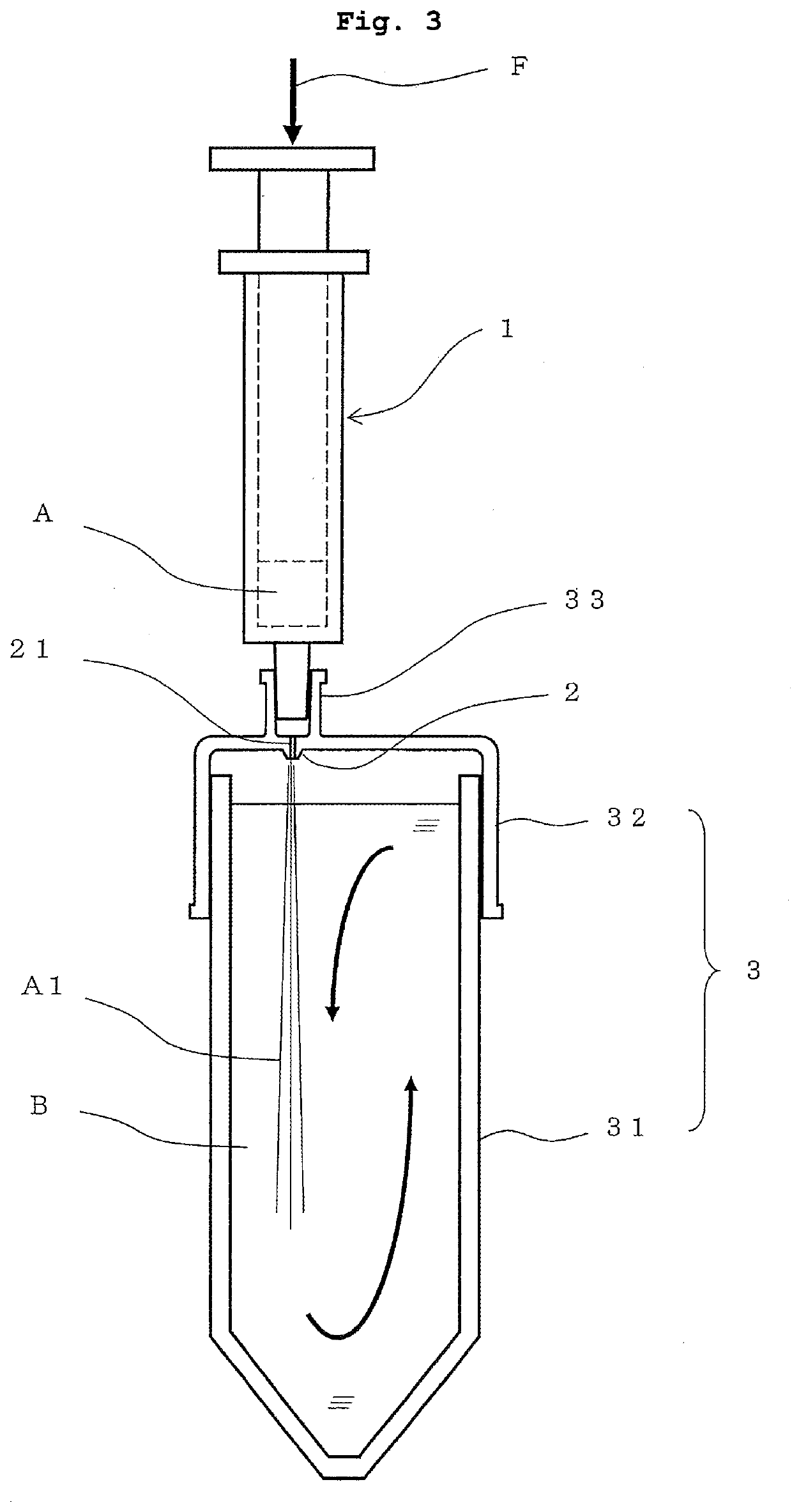
[0164]In Examples 1-9 and Comparative Examples 1-16, a production device of the type shown in FIG. 3 was produced.
[0165]As a container, the body part o...
experimental example 2
Diameter of Through-Hole of Nozzle Part
[0184]In Experimental Example 2, the same amount of the first liquid is injected by the same pressing force from a syringe with the same specifications, and changes in the flow rate and flow velocity, and the dispersed state (suspending property) of the beads and the state of the structure (precipitate) as in the above-mentioned Experimental Example 1 when the bore diameter of the through-hole of the nozzle part was stepwisely changed were evaluated.
[0185]The first liquid, syringe, the second liquid, and conical tube used were the same as those in the above-mentioned Experimental Example 1. In Experimental Example 2, to stepwisely change the bore diameter of the through-hole of the nozzle part, injection needles of various gauges (inner diameter) were mounted on the syringe tip. That is, in this Experimental Example, the inner passage of the injection needle is the through-hole. The criteria of the evaluation of the dispersed state (suspending ...
experimental example 3
t Direction of the First Liquid
[0194]In Experimental Example 2, in injecting the first liquid from the syringe into the container, whether the dispersed state of the beads (suspending property) varies between an injection direction of from the top to the lower side, and an injection direction of from the bottom to the upper side by setting the container upside down, was evaluated.
[0195]The first liquid, syringe, second liquid, and conical tube used were the same as those in the above-mentioned Experimental Example 1.
[0196]The dispersed state (suspending action) of beads in each Experimental Example is shown in Table 5.
TABLE 5DAGsecond liquidamount offinaltemperatureamountfirst liquidconcentrationcontainer, syringesuspendingNo.kind[° C.][mL][mL][wt %]orientation when mixingactionnotea1DEEM-h4400.80.01550 mL tube, 1 mL syringe∘goodinjected from topa2DEEM-h4400.80.01550 mL tube, 2.5 mL syringe∘goodinjected from bottoma3DEEM-h4400.80.01550 mL tube, 1 mL syringe∘goodinjected from bottoma...
PUM
| Property | Measurement | Unit |
|---|---|---|
| flow rate | aaaaa | aaaaa |
| flow rate | aaaaa | aaaaa |
| discharge flow rate | aaaaa | aaaaa |
Abstract
Description
Claims
Application Information
 - R&D
- Intellectual Property
- Life Sciences
- Materials
- Tech Scout
- Unparalleled Data Quality
- Higher Quality Content
- 60% Fewer Hallucinations
Browse by: Latest US Patents, China's latest patents, Technical Efficacy Thesaurus, Application Domain, Technology Topic, Popular Technical Reports.
© 2025 PatSnap. All rights reserved.Legal|Privacy policy|Modern Slavery Act Transparency Statement|Sitemap|About US| Contact US: help@patsnap.com


