Systems and methods for vehicle control using terrain-based localization

a technology of system and terrain, applied in the field of system for terrain-based localization and insights, can solve the problems of insufficient accuracy or resolution of such features, poor visibility, and inability to provide such features with sufficient accuracy or resolution,

Pending Publication Date: 2022-09-08
CLEARMOTION INC
View PDF0 Cites 17 Cited by
  • Summary
  • Abstract
  • Description
  • Claims
  • Application Information

AI Technical Summary

Benefits of technology

[0064]Intelligent Speed Adaptation systems warn or enforce driving speed based on a speed limit and / or upcoming road information. The Inventors have recognized that driving speed recommendations for safety, comfort, and / or vehicle durability may be determined with foresight of one or more upcoming road conditions. Upcoming road conditions may include, but are not limited to, road events, road roughness, road frequency content, road friction, road curvature, weather dependent events, and / or average driving speed. With precise localization and data sharing with a database, a recommended driving speed, which may be based on foresight of upcoming road conditions, may be calculated, and served to an Intelligent Speed Adaptation system on vehicle. The Intelligent Speed Adaptation system then may warn and / or enforce the recommended driving speed to a driver of the vehicle to improve safety, comfort, fuel economy, range, and / or vehicle durability, or other desired metrics.
[0148]In some implementations, the impairment level of the operator is above a threshold. In some instances, the method also includes alerting the operator of the vehicle of the impairment level of the operator. In some instances, the method also includes alerting a vehicle controller of the impairment level of the operator. In some instances, the method also includes changing an operating mode of the vehicle based on the impairment level of the operator. In some instances, changing an operating mode of the vehicle includes activating an autonomous driving mode, activating a semi-autonomous driving mode, activating a lane keep assist feature, activating an adaptive cruise control feature, reducing a driving speed of the vehicle, and / or reducing a maximum driving speed of the vehicle.

Problems solved by technology

Localization systems based on, for example, global navigation satellite systems (GNSS), may not provide sufficient accuracy or resolution for such features.
In some implementations, the conditions of poor visibility are caused by fog and the at least one remote sensor is a radar detector.
The sensor systems used for this application are vulnerable to multiple potential failures, including sensor obscurement through reflections or dirt on the glass; sensor function reduction due to environmental conditions such as rain, fog, snow; and a possible general inability to identify lane markers, for example due to lighting problems such as darkness.
Sensor systems used for this application may be vulnerable to multiple potential failures, for example where lane markings are obstructed, obscured, or not present for short stretches of road, and may lead to an incorrect trajectory being commanded by the assist feature or autonomous driving planner.
Illuminating the road far ahead of the vehicle though may also have a negative impact, because the headlights will then also shine strong light onto oncoming vehicles, potentially obstructing the visibility of operators of such vehicles.
Another problem occurs when a vehicle is rounding a turn and the headlights are illuminating the section of road straight ahead of the vehicle and not the section of road which the vehicle is about to traverse.
When driving on a road that falls away in front of the vehicle, the headlights illuminate a section of road that is farther in front of the vehicle and potentially larger, but also potentially illuminating oncoming vehicles in an undesired manner.
Even using headlight systems described above, this problem cannot be solved, as the road ahead of the vehicle is not known and can, generally, not be sufficiently sensed with existing sensor systems such as vision-based systems, LiDAR, radar, or other known technologies.
This steering correction is often suggested to an operator through tactile feedback and / or performed by front steering actuators; however, this feedback may be intrusive or perceived by the driver as an uncomfortable pulling of the vehicle to one side or another.
In some implementations, the poor visibility may be caused by fog and the at least one remote sensor may be a radar detector.

Method used


Image

  • Systems and methods for vehicle control using terrain-based localization
  • Systems and methods for vehicle control using terrain-based localization
  • Systems and methods for vehicle control using terrain-based localization

Examples


Embodiment Construction

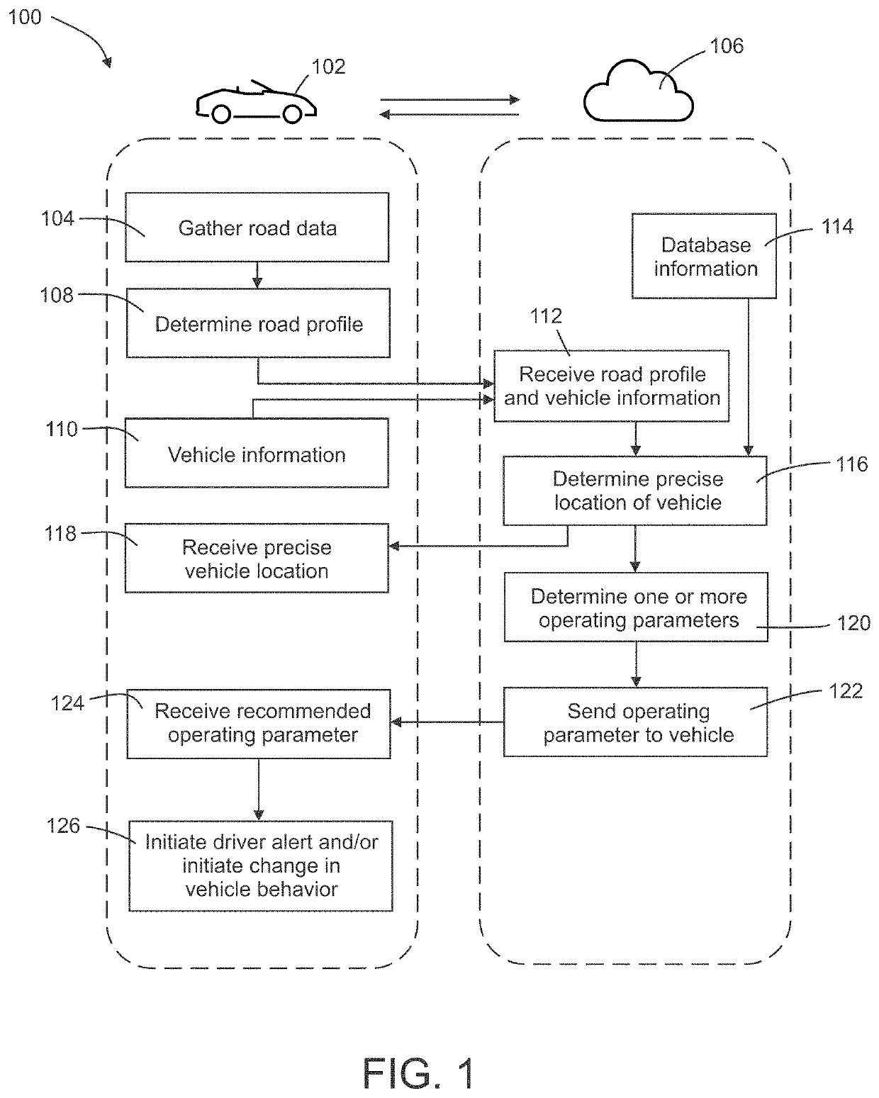
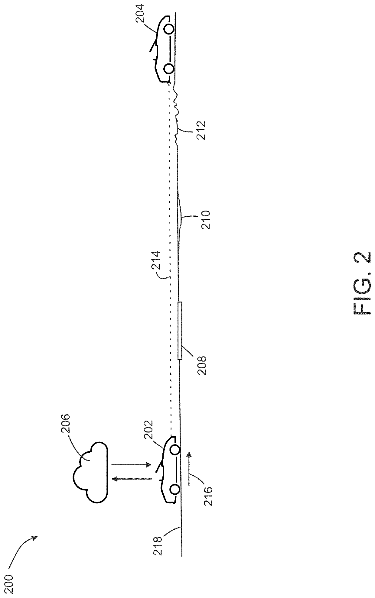
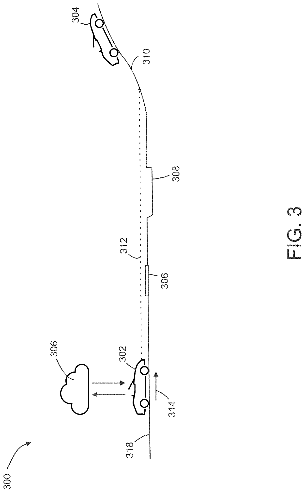
[0269]A vehicle traveling along a road, autonomously or under the control of a driver, may interact with one or more road surface features that may expose the vehicle and / or one or more vehicle occupants to certain forces or accelerations. Such road features may affect the comfort of vehicle occupants as well as wear-and-tear of the vehicle. The magnitude, direction, and / or frequency content of such forces or accelerations may be a function of the characteristics of one or more road surface features. A typical road may include various types of road surface features, such as for example, road surface anomalies including, but not limited to potholes, bumps, surface cracks, expansion joints, frost heaves, rough patches, rumble strips, storm grates, etc.; and / or road surface properties, including but not limited to road surface texture, road surface composition, surface camber, surface slope, etc. Road surface properties may affect road surface parameters, such for example, the friction...


PUM


Abstract

Systems and methods described herein include implementation of road surface-based localization techniques for advanced vehicle features and control methods including advanced driver assistance systems (ADAS), lane drift detection, passing guidance, bandwidth conservation and caching based on road data, vehicle speed correction, suspension and vehicle system performance tracking and control, road estimation calibration, and others.

Description

RELATED APPLICATIONS[0001]This application claims the benefit of priority under 35 U.S.C. § 119(e) of U.S. Provisional Application Ser. No. 63 / 130,028, filed Dec. 23, 2020, U.S. Provisional Application Ser. No. 63 / 132,184, filed Dec. 30, 2020, and U.S. Provisional Application Ser. No. 63 / 146,379, filed Feb. 5, 2021, the disclosures of which are incorporated herein by reference in their entirety.TECHNICAL FIELD[0002]Disclosed embodiments are related to systems for terrain-based localization and insights for systems in vehicles and related methods of use.BACKGROUND[0003]Advanced vehicle features such as, for example, advanced driver assistance systems, active suspension systems, and / or autonomous or semi-autonomous driving may rely on highly accurate localization of a vehicle. Localization systems based on, for example, global navigation satellite systems (GNSS), may not provide sufficient accuracy or resolution for such features.SUMMARY[0004]According to one aspect, the present discl...

Claims


Application Information

Patent Timeline
Patent Type & Authority Applications(United States)
IPC IPC(8): B60W30/18B60W40/06B60W50/16
CPCB60W30/18163B60W40/06B60W50/16B60W2050/146G06V20/58G08G1/096716G08G1/096741G08G1/09675G08G1/096775B60W2552/35B60W2552/15B60W2552/20B60W2552/40B60W2552/30B60W2720/10B60W2556/50B60W50/14B60W2555/20B60W2556/45B60W2554/802B60W2050/143B60W30/16B60W30/12B60W30/09B60W10/22G01S13/931G01S17/931G01S2013/9323G01S7/4021G01S2013/9325G01S7/4013G01S2013/9322G01S2013/9316G01S7/412G01S7/003G01S2013/93271B60W2422/70
Inventor GIOVANARDI, MARCOLIN, HOU-YISCHULZE, STEFANEISENMANN, JOHN PARKERGRAVES, WILLIAMPROCTOR, MARCUS JOSEPHKARAVAS, NIKOLAOSCHEN, ALLEN CHUNG-HAOEKCHIAN, JACK A.
Owner CLEARMOTION INC
Why Eureka
Try Eureka