Supercharge Your Innovation With Domain-Expert AI Agents!

Semiconductor device with edge-protecting spacers over bonding pad

a technology of semiconductor devices and bonding pads, which is applied in the direction of semiconductor devices, semiconductor/solid-state device details, electrical apparatus, etc., can solve the problems of poor electrical interconnection, complex manufacturing and integration of semiconductor devices, and many complicated steps and operations

Pending Publication Date: 2022-09-08
NAN YA TECH
View PDF3 Cites 0 Cited by
  • Summary
  • Abstract
  • Description
  • Claims
  • Application Information

AI Technical Summary

Benefits of technology

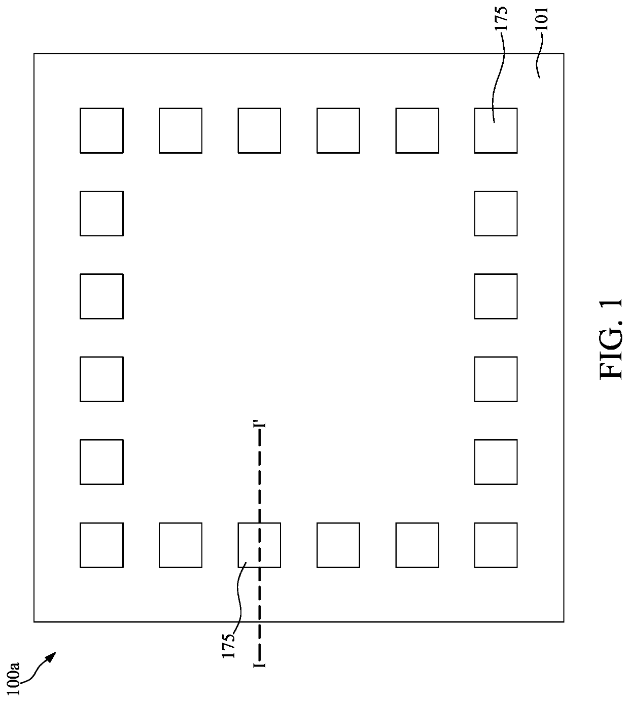
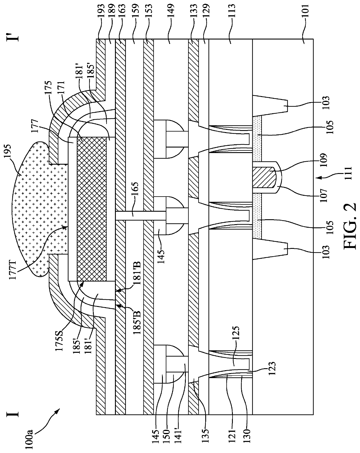
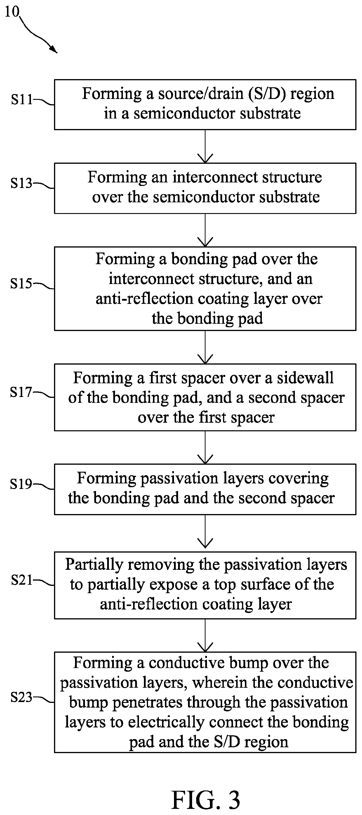
[0026]Embodiments of a semiconductor device are provided in accordance with some embodiments of the disclosure. The semiconductor device includes a second spacer over a sidewall of a bonding pad, a first passivation layer covering the bonding pad and the second spacer, and a conductive bump over the first passivation layer and electrically connected to a source / drain region in an underlying semiconductor substrate through the bonding pad. As a result of such configuration, short circuit problems caused by misalignment of the bonding pad and the conductive bump may be prevented by the second spacer. Accordingly, the overall device performance may be improved, and the yield rate of the semiconductor device may be increased.

Problems solved by technology

However, the manufacturing and integration of semiconductor devices involve many complicated steps and operations.
An increase in complexity of manufacturing and integration of the semiconductor device may cause deficiencies such as poor electrical interconnection, misalignment of bonding components, or moisture-induced deterioration.

Method used


Image

  • Semiconductor device with edge-protecting spacers over bonding pad
  • Semiconductor device with edge-protecting spacers over bonding pad
  • Semiconductor device with edge-protecting spacers over bonding pad

Examples


Embodiment Construction

[0054]The following disclosure provides many different embodiments, or examples, for implementing different features of the provided subject matter. Specific examples of components and arrangements are described below to simplify the present disclosure. These are, of course, merely examples and are not intended to be limiting. For example, the formation of a first feature over or on a second feature in the description that follows may include embodiments in which the first and second features are formed in direct contact, and may also include embodiments in which additional features may be formed between the first and second features, such that the first and second features may not be in direct contact. In addition, the present disclosure may repeat reference numerals and / or letters in the various examples. This repetition is for the purpose of simplicity and clarity and does not in itself dictate a relationship between the various embodiments and / or configurations discussed.

[0055]F...


PUM

PropertyMeasurementUnit
conductiveaaaaaaaaaa
sizeaaaaaaaaaa
structureaaaaaaaaaa

Abstract

The present application provides a semiconductor device with an edge-protecting spacer over a bonding pad. The semiconductor device includes a bonding pad disposed over a semiconductor substrate; a first spacer disposed over a top surface of the bonding pad; a dielectric liner disposed between the first spacer and the bonding pad; a dielectric layer between the bonding pad and the semiconductor substrate, wherein the dielectric layer includes silicon-rich oxide; and a conductive bump disposed over the bonding pad and covering the first spacer and the dielectric liner, wherein the conductive bump is electrically connected to a source / drain (S / D) region in the semiconductor substrate through the bonding pad.

Description

CROSS-REFERENCE TO RELATED APPLICATION[0001]This application is a divisional application of U.S. Non-Provisional application Ser. No. 16 / 678,134 filed 8 Nov. 2019, which is incorporated herein by reference in its entirety.TECHNICAL FIELD[0002]The present disclosure relates to a semiconductor device, and more particularly, to a semiconductor device with an edge-protecting spacer over a bonding pad.DISCUSSION OF THE BACKGROUND[0003]Semiconductor devices are essential for many modern applications. With the advancement of electronic technology, semiconductor devices are becoming smaller in size while providing greater functionality and comprising greater amounts of integrated circuitry. Due to the miniaturized scale of semiconductor devices, various types and dimensions of semiconductor devices performing different functions are integrated and packaged into a single module. Furthermore, numerous manufacturing operations are implemented for integration of various types of semiconductor d...

Claims


Application Information

Patent Timeline
Patent Type & Authority Applications(United States)
IPC IPC(8): H01L23/00H01L23/522H01L23/532H01L21/768H01L29/417
CPCH01L24/05H01L23/5226H01L24/13H01L23/53295H01L21/7682H01L21/76885H01L24/03H01L29/41725H01L2224/05573H01L29/4236H01L24/04H01L2224/0401H01L2224/0554H01L2224/05541H01L2224/0556H01L21/76831H01L2221/1063H01L23/485H01L23/5222H01L29/78H01L2224/13H01L2224/03019H01L2224/0391H01L2224/02206H01L2224/02215H01L2224/02181H01L2224/0217H01L2224/0219H01L2224/02185H01L2224/10135H01L2224/05007
Inventor CHIEN, JUNG-HSING
Owner NAN YA TECH
Features
  • R&D
  • Intellectual Property
  • Life Sciences
  • Materials
  • Tech Scout
  • Unparalleled Data Quality
  • Higher Quality Content
  • 60% Fewer Hallucinations
Learn More