
Electrical power control system

Pending Publication Date: 2022-09-29
HONDA MOTOR CO LTD
View PDF2 Cites 0 Cited by
  • Summary
  • Abstract
  • Description
  • Claims
  • Application Information

AI Technical Summary

Benefits of technology

The patent text describes a system for controlling the voltage in a fuel cell system to enhance the output efficiency during startup. The technical effect of the patent is to improve the efficiency of the fuel cell system during startup without the need for a complex control system.

Problems solved by technology

In such an electrical power control system, in particular, since a VCU is provided in each of the fuel cell systems, the output efficiency is significantly reduced.

Method used


Image

  • Electrical power control system
  • Electrical power control system
  • Electrical power control system

Examples


Embodiment Construction

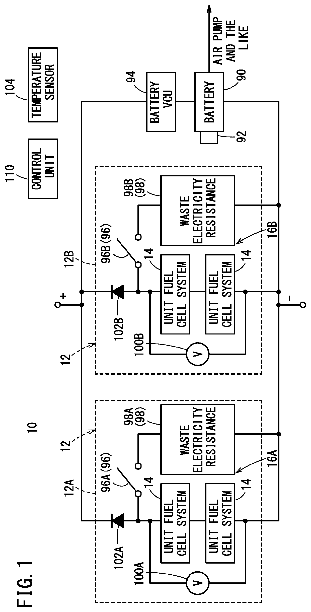
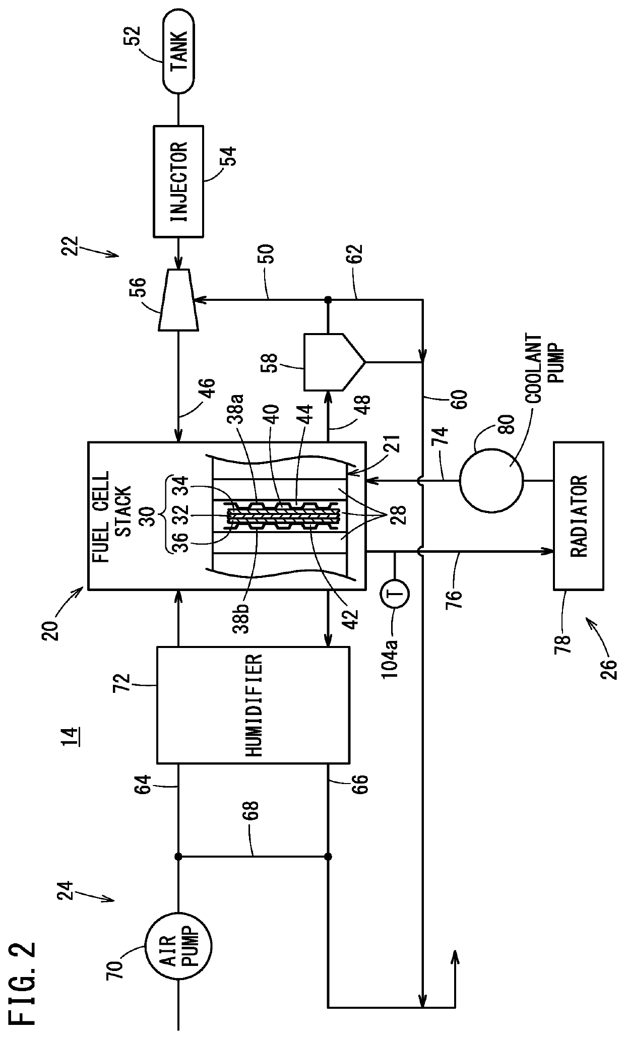
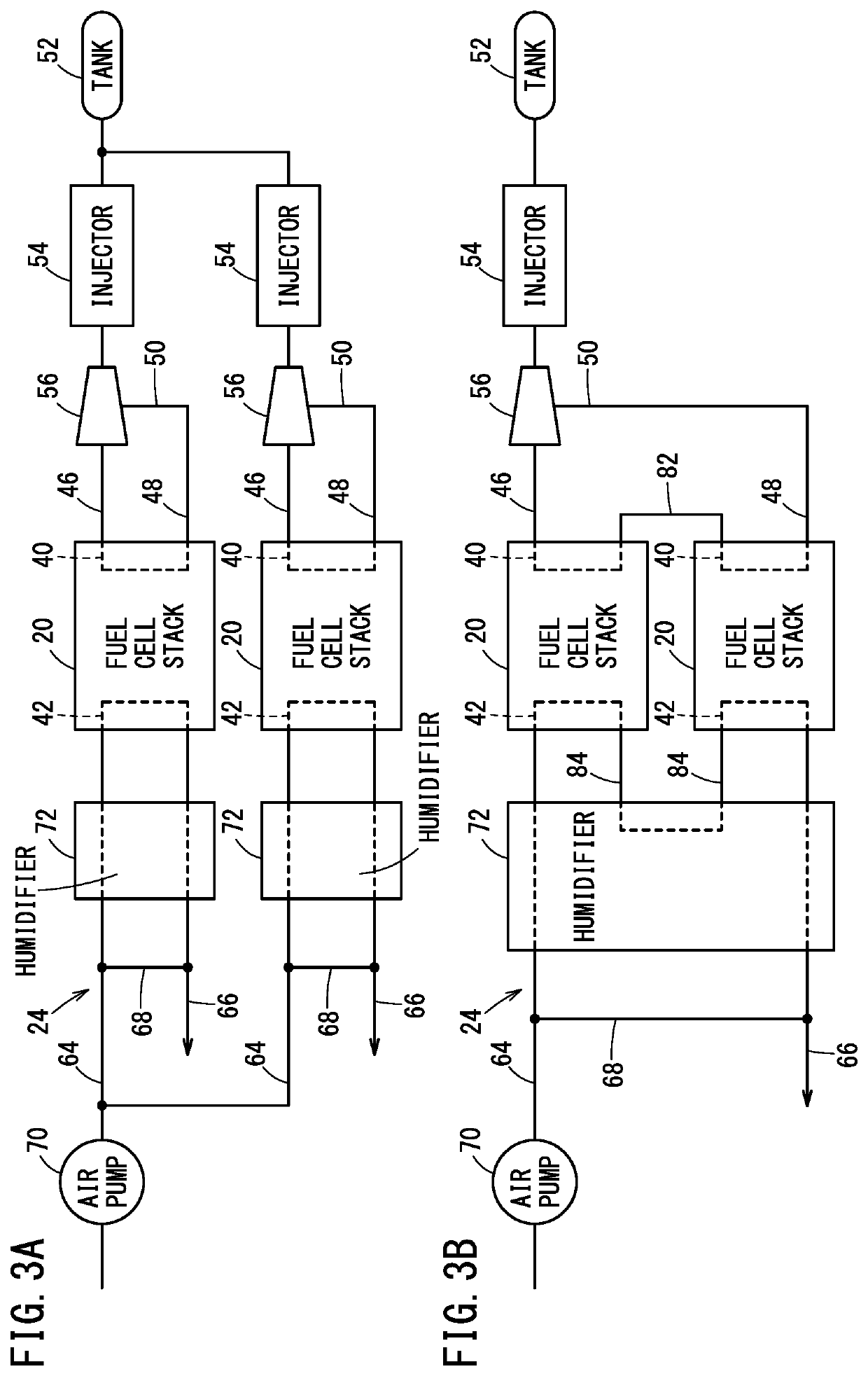
[0022]As shown in FIG. 1, an electrical power control system 10 according to an embodiment of the present invention is equipped with a plurality of power supply systems 12 (two are shown in FIG. 1). The electrical power of the plurality of power supply systems 12 is capable of being controlled. At least one fuel cell system is provided in the interior of each of the power supply systems 12. Hereinafter, one of the fuel cell systems will be referred to as a unit fuel cell system 14. The unit fuel cell system 14 generates electrical power based on supplying of a fuel gas (hydrogen gas) and an oxygen containing gas (oxygen gas, air), and outputs the generated electrical power. This type of electrical power control system 10 is applied, for example, to a large scale movable body (a bus, a freight vehicle, a ship, an airplane, or the like) for which a high voltage and a high current are required. It should be noted that the target object to which the electrical power control system 10 is...


PUM


Abstract

An electrical power control system includes a first fuel cell system and a second fuel cell system, and a waste electricity unit connected in series with a switch unit. The waste electricity unit and the switch unit are connected in parallel with each of the fuel cell systems. At a time when at least one power supply system is started, a control unit selectively executes a charging control and a waste electricity control, based on at least one of temperature information and electrical storage information. The charging control suppresses a rise in voltage by supplying the electrical power of the power supply system to the power storage device. The waste electricity control suppresses a rise in voltage by supplying the electrical power of the power supply system to the waste electricity unit.

Description

CROSS-REFERENCE TO RELATED APPLICATIONS[0001]This application is based upon and claims the benefit of priority from Japanese Patent Application No. 2021-052610 filed on Mar. 26, 2021, the contents of which are incorporated herein by reference.BACKGROUND OF THE INVENTIONField of the Invention[0002]The present invention relates to an electrical power control system configured to control a voltage at a time when a fuel cell system is started.Description of the Related Art[0003]As disclosed in JP 2020-031030 A, an electrical power control system having a fuel cell system controls a generated voltage of a fuel cell stack by way of a VCU (voltage conversion unit), for example, a DC / DC converter.SUMMARY OF THE INVENTION[0004]Incidentally, in such a voltage control system, when the voltage is adjusted by the VCU which is provided in the fuel cell system, the output efficiency of the electrical power at the time of starting is lowered. In JP 2020-031030 A, an electrical power control system ...

Claims


Application Information

Patent Timeline
IPC IPC(8): H01M16/00H01M8/04858H01M8/04302
CPCH01M16/006H01M8/0494H01M8/0488H01M8/04302H02J7/00036H02J7/0013H02J7/007H02J7/00712H02J7/007182Y02T90/40Y02E60/50
Inventor IGUCHI, TSUYOSHI
Owner HONDA MOTOR CO LTD
Learn More