Self-propelled earth working machine including combined heat exchanger cooling and engine compartment ventilation

a self-propelled earth working machine and engine compartment technology, which is applied in the direction of machines/engines, roads, roads, etc., can solve the problems of reducing the heat dissipation of cooling medium to air at the heat exchanger and thus the heat exchanger's efficiency, and the hydraulic oil of the hydraulic motor is subject to a great thermal load. , to achieve the effect of good efficiency factor and low emissions

Pending Publication Date: 2022-10-06
WIRTGEN GMBH
View PDF0 Cites 0 Cited by
  • Summary
  • Abstract
  • Description
  • Claims
  • Application Information

AI Technical Summary

Benefits of technology

[0022]Another advantage of the invention is the fact that only a portion of the total air quantity conveyed by the ventilator system is aspirated from the ventilation volume near the power source, which reduces the underpressure in the surroundings of the power source and thus the entry of dirt into these surroundings compared to the related art according to EP 3 081 421 B1 (U.S. Pat. No. 10,294,850).
[0023]The point of origin of both the cooling air flow as well as the ventilation air flow is preferably the external environment and thus the surrounding atmosphere of the earth working machine, without one of the air flows absorbing heat convectively from another functional device prior to reaching the heat exchanger system or the power source. At most, air aspirated by the ventilator system flows through a cover of the heat exchanger system and / or a cover of the power source from the external surroundings toward the heat exchanger system or toward the power source.
[0024]The power source is preferably a combustion engine, the combustion engine in turn being preferably a diesel combustion engine. Diesel combustion engines may be operated in stationary fashion with a good efficiency factor and low emissions. It shall not be excluded, however, that an Otto engine or another kind of thermal or electrical motor is used as power source or that the power source comprises one or multiple fuel cells. The power source may be in particular a combustion engine including turbocharger. The power source is, as it were, a power plant incorporated in the earth working machine, which provides the power required for operating the earth working machine. In the case of a thermal engine as power source, the earth working machine may comprise in a manner known per se one or multiple power converters, which convert the power provided in one form by the power source into another form of provided power. Thus it is possible for example to drive the working apparatus for earth working mechanically by a mechanical output member of the power source, such as a crankshaft, by connecting gears in between. It is likewise possible, for example via a secondary output shaft of such a gear, in particular of a pump transfer gear, to operate a hydraulic pump, which converts the power provided by the power source into potential energy in the form of an increased pressure level of a hydraulic oil. Furthermore, power of the power source may be converted via a generator from mechanical power into electrical power.
[0025]According to a more generalized teaching of the present invention, instead of the power source, a heat source may be situated separately from the heat exchanger system, and preferably at a distance from the latter, leading away from which the ventilator system generates a ventilation air flow in operation in order to ventilate the heat source. What was said in the present application about the power source also applies to the heat source, which may be for example an electrical energy storage system or a gear unit.
[0026]The working apparatus for earth working is preferably an earth-removing working apparatus. This is preferably understood to be a rotating working apparatus having geometrically defined bits, such as for example a milling drum, and / or having geometrically undefined bits, such as for example a so-called “grinding drum” for a specific texturing of earth surfaces.
[0027]In the present context, a “passing” of the cooling air flow past the heat exchanger system denotes any kind of flow of the cooling air flow past the heat exchanger system while the cooling air flow is convectively removing heat from the heat exchanger system. When passing the heat exchanger system, the cooling airflow may flow along a heat transfer surface of the heat exchanger system in the same direction or in the opposite direction relative to the direction of flow of a cooling medium flowing on the other side of the heat transfer surface. The heat exchanger system is preferably a cross-flow heat exchanger system, in which the cooling air flow flows crosswise with respect to the direction of flow of the cooling medium flowing through the heat exchanger system. The heat exchanger system may have cooling ducts carrying the cooling air flow.

Problems solved by technology

In a travel operation without earth working, there is only little thermal load on the combustion engine and its cooling medium, while there is a great load on the hydraulic oil of the hydraulic motors forming the travel drive.
In an earth working operation at low travel speeds, compared to the aforementioned travel operation, but at a high drive output of the milling drum of the cold milling machine, there is only little thermal load on the hydraulic oil, while there is a great thermal load on the combustion engine and its cooling medium.
The first mentioned technical teaching has the disadvantage that the air moved through the heat exchanger has a higher temperature than the aspirated pure fresh air due to the admixed heated air that was vented from the area of the combustion engine, which reduces the heat dissipation from cooling medium to air at the heat exchanger and thus the heat exchanger's efficiency.
The second mentioned technical teaching has the one disadvantage that ventilators operated so as to push the air are less efficient than ventilators operated with the same power in sucking fashion and has the further disadvantage that at the pressure side particularly the air moved toward the combustion engine in pushing fashion flows along nearly uncontrollable and unpredictable flow routes and exits at arbitrary often even disadvantageous locations at the earth working machine into the outer surroundings.
Consequently, the ventilator system conveys air heated by the combustion engine through the heat exchanger system, which results in the disadvantages described above.

Method used


Image

  • Self-propelled earth working machine including combined heat exchanger cooling and engine compartment ventilation
  • Self-propelled earth working machine including combined heat exchanger cooling and engine compartment ventilation
  • Self-propelled earth working machine including combined heat exchanger cooling and engine compartment ventilation

Examples


Embodiment Construction

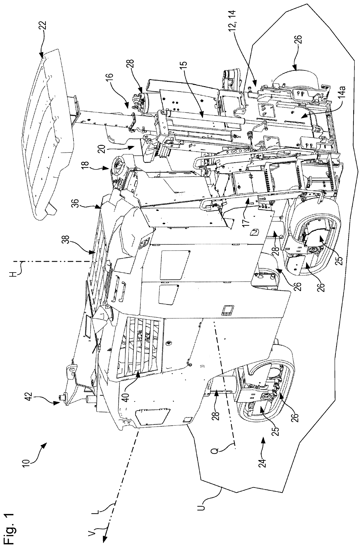
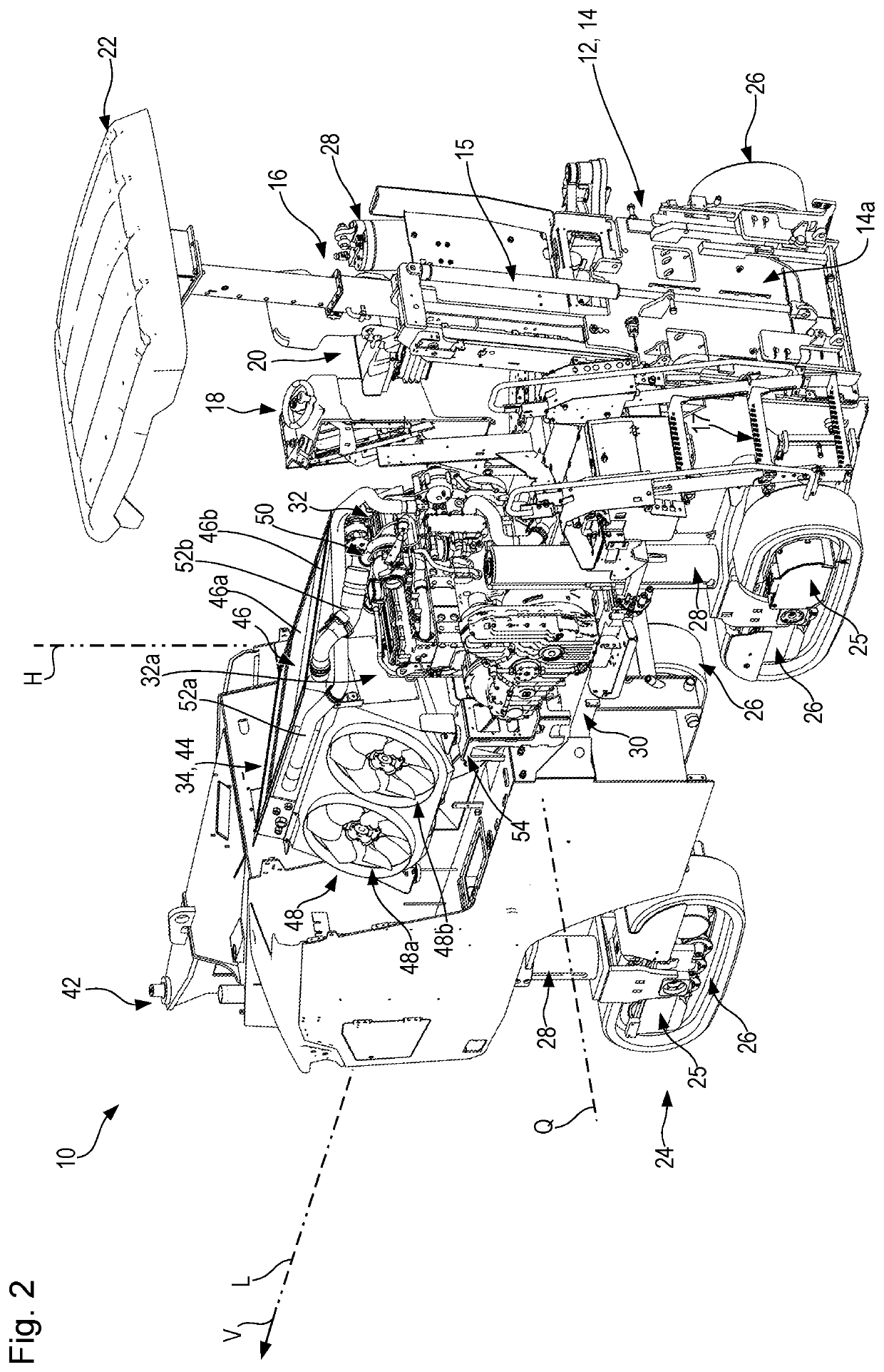
[0067]In FIGS. 1 and 2, a cold milling machine in the merely exemplary form of a compact milling machine is shown at an angle from the rear and generally labeled with reference numeral 10. In the concretely illustrated compact milling machine, the working apparatus 12 is located in a milling drum housing 14 in the rear area of cold milling machine 10, approximately below an operator's platform situated asymmetrically offset to the right side of the machine when viewed in the forward travel direction, which is reachable via a ladder 17 at the rear of the machine and from which the operation of cold milling machine 10 may be controlled by a machine operator. At the rear of cold milling machine 10, a scraper shield 14a may be seen, which may be raised and lowered via a piston-cylinder actuator 15 and which forms the rear wall of milling drum housing 14.

[0068]For operating a control console 18, the machine operator may sit on a driver's seat 20 and is in so doing protected against preci...


PUM


Abstract

A self-propelled earth working machine includes a traveling gear, a machine frame supported by the traveling gear, a power source accommodated on the machine frame for providing power for a travel operation and / or for an earth working operation, a working apparatus accommodated on the machine frame for earth working, and a cooling device for cooling a functional device of the earth working machine. The cooling device includes at least one heat exchanger system for transferring heat from a cooling medium to air, and a ventilator system, which is on the one hand designed and situated to produce a cooling air flow passing the heat exchanger system and which is on the other hand designed and situated to produce in the area of the power source a ventilation air flow flowing away from the power source. The heat exchanger system and a ventilation volume, in which the ventilation air flow flows away from the power source, are situated on the suction side of the ventilator system, the ventilation volume being situated downstream of the heat exchanger system relative to the cooling air flow, so that the ventilation air flow generated by the ventilator system meets the cooling air flow downstream of the heat exchanger system and upstream of the ventilator system.

Description

RELATED APPLICATIONS[0001]This application claims priority to German application DE 10 2021 108 113.0 filed Mar. 30, 2021, which is incorporated herein by reference.BACKGROUND OF THE INVENTIONField of the Invention[0002]The present invention relates to a self-propelled earth working machine, such as for example a road milling machine, in particular a cold milling machine, a surface miner or a stabilizer. The earth working machine comprises:[0003]a traveling gear, by which the earth working machine stands on a subsurface in rollable fashion, and[0004]a machine frame supported by the traveling gear,[0005]a power source accommodated on the machine frame for providing power, which is usable for a travel operation and / or for an earth working operation of the earth working machine,[0006]a working apparatus for earth working accommodated on the machine frame,[0007]a cooling device for cooling a functional device of the earth working machine, the cooling device comprising:[0008]at least one...

Claims


Application Information

Patent Timeline
Patent Type & Authority Applications(United States)
IPC IPC(8): B60K11/04E01C23/088E01C23/12
CPCB60K11/04E01C23/088E01C23/127F01P5/02E01C23/0885E01C23/06F01P11/10F01P3/18F01P5/06F01P1/00B60K11/06B60K11/02F01P2003/185F01P2005/025F01P2060/02B60K11/08B60Y2200/41
Inventor STINNER, TOBIASSTREMEL, VIKTORMAHLBERG, AXELYANZA, ROLF DAVID PANCHO
Owner WIRTGEN GMBH
Why Eureka
Try Eureka