
Eureka
For R&D, Eureka makes reading and utilizing patents & technical documents easy.
Eureka AIR
Designed for self-driven R&D workflows. Generate viable solutions, solve complex R&D challenges, empower your innovation with AI.

Eureka Materials
Designed for material experts only. Revolutionize your material R&D, from search, analyze, to developing new materials.

TechResearch
Generate reliable direction feasibility study reports for your R&D in just a few steps.

TechSeek
Discover and master advanced knowledge NOW. Basics, ideas, possibilities, all at once.

TechMind
As an expert in R&D Theories, TechMind can generates customized viable solutions instantly.

TechRisk
Analyze your overall solution with one click, know your potential R&D risks in advance.

TechMonitor
Get weekly tech updates, stay abreast of the latest tech innovations and key insights.
Electrical Switch
- Summary
- Abstract
- Description
- Claims
- Application Information
AI Technical Summary
Benefits of technology
Problems solved by technology
Method used
Image

Examples
first example of an embodiment
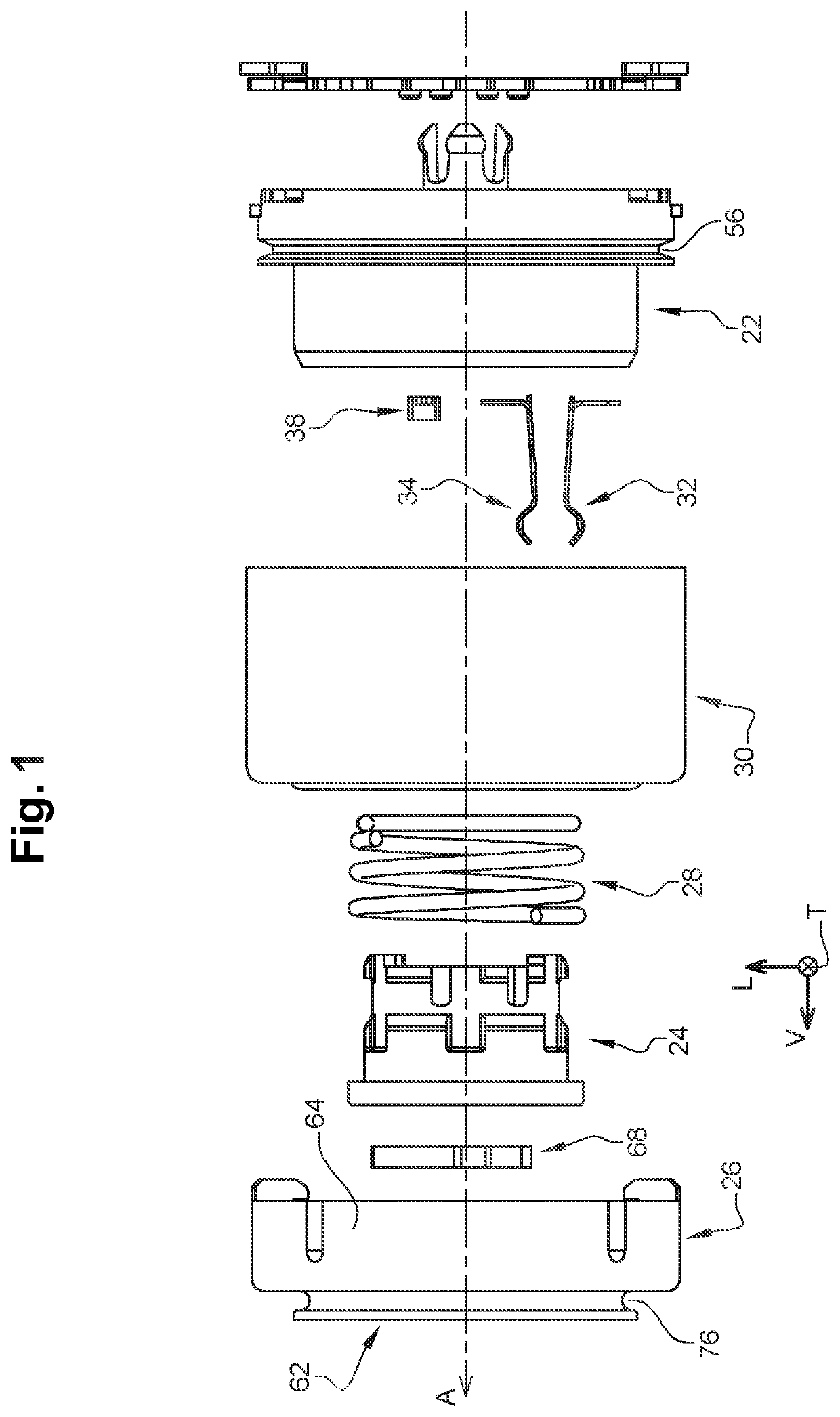
[0037]In the following example, the electrical switch 20 is generally symmetrical in design with respect to the median vertical and longitudinal plane, and with respect to the median vertical and transverse plane.
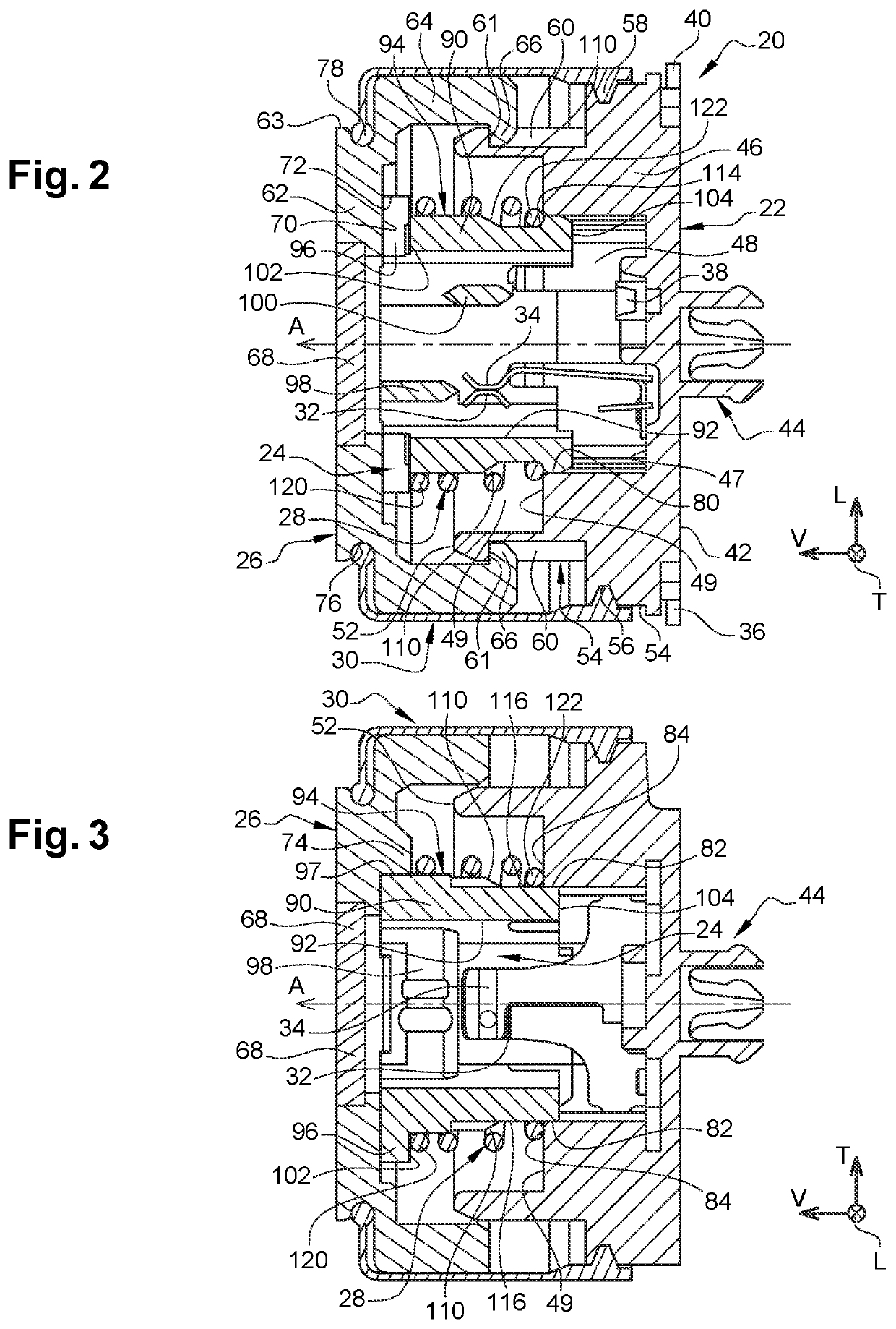
[0038]Vertically from bottom to top, the electrical switch 20—which is illustrated in particular in FIGS. 1 to 3—comprises a lower base 22 and an upper actuating rod 24 which is mounted so as to be slidable, along the main vertical axis A, relative to the lower base 22.
[0039]The lower base 22, which forms a housing, is closed at the top by an upper actuating cover 26, which is mounted so as to be axially displaceable relative to the lower base 22.
[0040]The electrical switch 20 further comprises a compression coil spring 28 which is axially interposed between the upper actuating rod 24 and the lower base 22, and a flexible lateral sealing membrane 30 which cooperates with the upper actuating cover 26 and the lower base 22.
[0041]The electrical switch 20 also comprises two ela...
second example embodiment
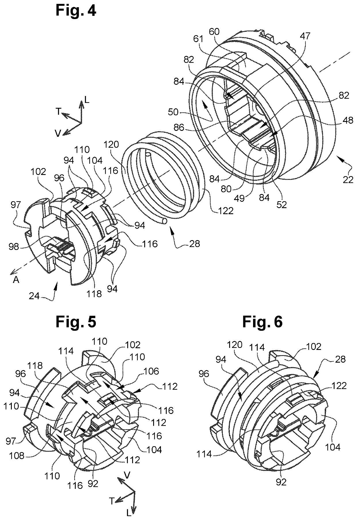
[0084]The second embodiment shown in FIG. 10 is similar to that shown in FIG. 9, except that the last turn 122 of the return spring 28 is generally circular in shape. Otherwise, as with the first embodiment shown in FIG. 9, the abutment facet 84 of axial rib 82, as well as the guiding bore 80. vertical axial grooves 116, lower base 22 and other elements of the switch, are arranged as they are in the first embodiment of FIGS. 1-9.
[0085]Thus, when the switch is actuated and the upper actuating rod 24 is pushed axially downwards against the elastic return force applied to it by the spring 28, the last turn 122 is supported axially on the facets 84 without any risk of this turn 122 becoming jammed between the upper actuating rod 24 and the lower base 22, even when the last turn 122 cooperates with the cam profile constituted by the frustoconical ramp 110.
PUM
 Abstract
Description
Claims
Application Information
 - R&D Engineer
- R&D Manager
- IP Professional
- Industry Leading Data Capabilities
- Powerful AI technology
- Patent DNA Extraction
Browse by: Latest US Patents, China's latest patents, Technical Efficacy Thesaurus, Application Domain, Technology Topic, Popular Technical Reports.
© 2024 PatSnap. All rights reserved.Legal|Privacy policy|Modern Slavery Act Transparency Statement|Sitemap|About US| Contact US: help@patsnap.com