Transmitter, receiver, transmission method, reception method, non-transitory computer readable storage medium, and integrated circuit
a computer readable storage medium and transmission method technology, applied in the field of transmission methods, receivers, transmission methods, reception methods, etc., can solve the problems of high power consumption, high cost, and comparatively high power consumption, so as to prevent the influence of quantization errors and reduce the number of bits of dac or ad
- Summary
- Abstract
- Description
- Claims
- Application Information
AI Technical Summary
Benefits of technology
Problems solved by technology
Method used
Image


Examples
first exemplary embodiment
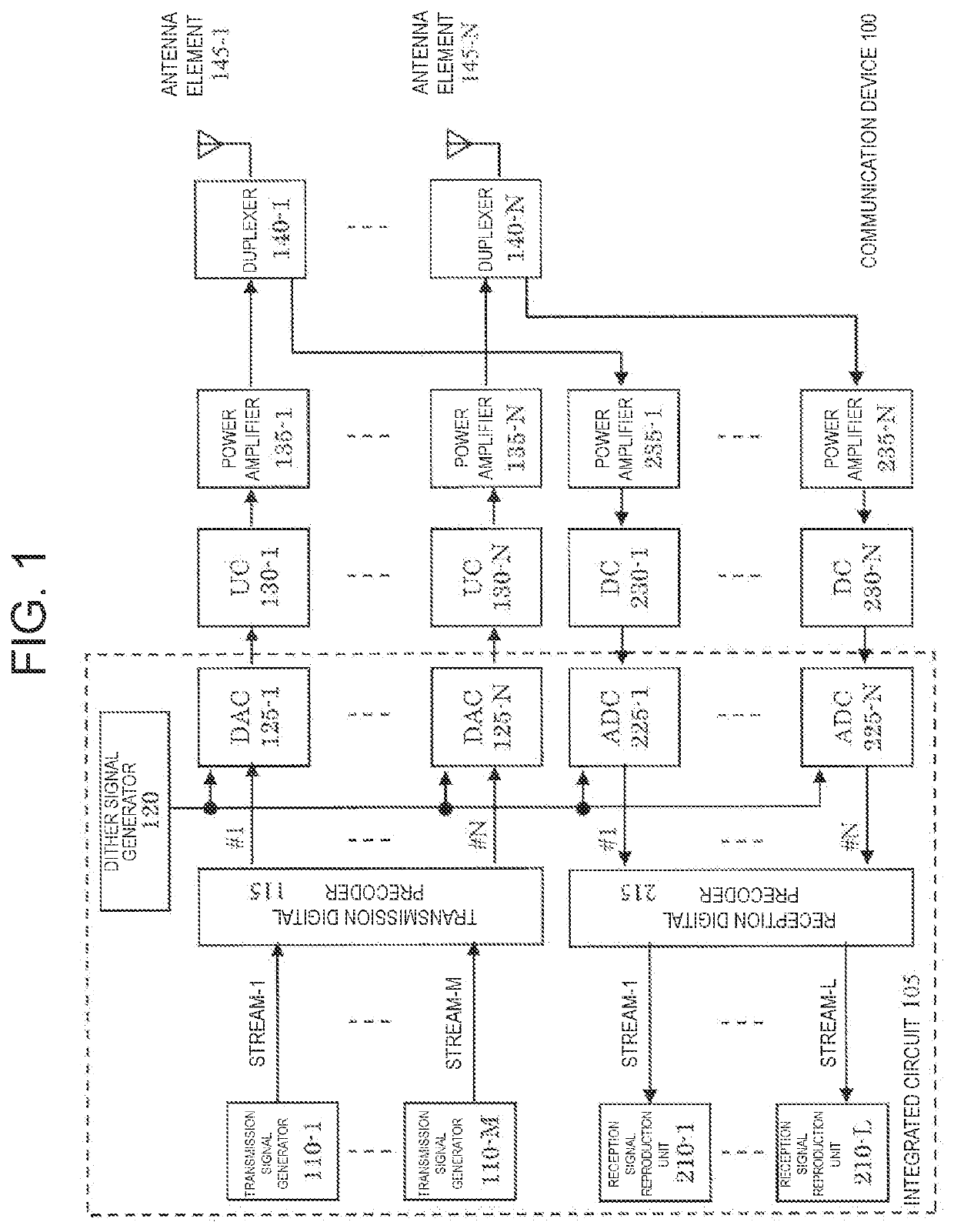
[0038]FIG. 1 is a diagram illustrating a configuration of communication device 100. Communication device 100 includes M transmission signal generators 110-1 to 110-M, transmission digital precoder 115, dither signal generator 120, N digital-to-analog converters (DACs) 125-1 to 125-N, N up converters (UCs) 130-1 to 130-N, N power amplifiers 135-1 to 135-N, N duplexers 140-1 to 140-N, N antenna elements 145-1 to 145-N, L reception signal reproduction units 210-1 to 210-L, reception digital precoder 215, N analog-to-digital converters (ADCs) 225-1 to 225-N, N down converters (DCs) 230-1 to 230-N, and N power amplifiers 235-1 to 235-N. Note that, in communication device 100, components that perform digital processing may be integrated circuit 105. Examples of the components that perform the digital processing include transmission signal generators 110-1 to 110-M, transmission digital precoder 115, dither signal generator 120, DACs 125-1 to 125-N, reception signal reproduction units 210-...
second exemplary embodiment
[0047]FIG. 6 is a diagram illustrating a configuration of communication device 300 according to a second exemplary embodiment of the present disclosure. The same components as those of communication device in the first exemplary embodiment are denoted by the same reference numerals, and the description thereof will be omitted. In the second exemplary embodiment, control of a valid antenna element enables sophisticated and low power beamforming.
[0048]As compared with communication device 100 in the first exemplary embodiment illustrated in FIG. 1, communication device 300 in FIG. 6 is configured to have transmission digital precoder 315, dither signal generator 320, N DACs 325-1 to 325-N, N UCs 330-1 to 330-N, N power amplifiers 335-1 to 335-N, reception digital precoder 415, N ADCs 425-1 to 425-N, N DCs 430-1 to 430-N, and N power amplifiers 435-1 to 435-N instead of transmission digital precoder 115, dither signal generator 120, N DACs 125-1 to 125-N, N UCs 130-1 to 130-N, N power ...
third exemplary embodiment
[0061]FIG. 11 is a diagram illustrating a configuration of communication device 500 according to a third exemplary embodiment of the present disclosure. The same components as those of communication device according to the first exemplary embodiment are denoted by the same reference numerals, and the description thereof will be omitted. In the third exemplary embodiment, the beamforming performance is kept constant by high-speed and real-time calibration by using both calibration signals and dither signals.
[0062]As compared with communication device 100 in the first exemplary embodiment illustrated in FIG. 1, communication device 500 in FIG. 11 has a configuration further including N transmission characteristics compensators 575-1 to 575-N, transmission characteristics calculation analog unit 580, reception characteristics calculation analog unit 585, transmission and reception characteristics calculator 590, N adders 595-1 to 595-N, and N reception characteristics compensators 675-...
PUM
 Abstract
Description
Claims
Application Information
 - R&D
- Intellectual Property
- Life Sciences
- Materials
- Tech Scout
- Unparalleled Data Quality
- Higher Quality Content
- 60% Fewer Hallucinations
Browse by: Latest US Patents, China's latest patents, Technical Efficacy Thesaurus, Application Domain, Technology Topic, Popular Technical Reports.
© 2025 PatSnap. All rights reserved.Legal|Privacy policy|Modern Slavery Act Transparency Statement|Sitemap|About US| Contact US: help@patsnap.com