Supercharge Your Innovation With Domain-Expert AI Agents!

Power spectral shaping for in-band emission control

a power spectral shaping and emission control technology, applied in the field of transmitter circuits, can solve the problems of reducing electromagnetic capability (emc), affecting the operation of other electronic devices within the vehicle, and/or roadside, and affecting the operation of other electronic devices

Pending Publication Date: 2022-10-13
AVAGO TECH INT SALES PTE LTD
View PDF0 Cites 0 Cited by
  • Summary
  • Abstract
  • Description
  • Claims
  • Application Information

AI Technical Summary

Benefits of technology

The patent text describes a method for easily creating a desired target spectral distribution using a UTP cable. This cable is cheaper, lighter, and can be bent with smaller radii without getting damaged. This makes it ideal for use in automotive applications. The technical effect of this invention is the creation of a versatile and cost-effective communication system.

Problems solved by technology

Every operating electronic device and in particular an electronic device operating with Radio Frequency (RF) signals contributes to a typically unwanted emission of electromagnetic radiation not only within but also outside from the automotive vehicle.
In this context it is clear that any unchecked electromagnetic emission generated by an electronic device within an automotive vehicle can negatively impact the operation of other electronic devices within an automotive vehicle and / or roadside equipment being external from the automotive vehicle.
One particularly serious problem of automotive vehicles are unwanted RF emissions within a frequency range being used for Digital Audio Broadcasting (DAB) operating between 174 MHz and 239 MHz and / or frequency modulated (FM) radio systems such as metric wave systems operating between about 65 MHz and 108 MHz.
This problem of a reduced electromagnetic capability (EMC) is especially serious when Unshielded Twisted Pair (UTP) cables are used, which compared to Shielded Twisted Pair (STP) cables are often preferred because STP have a higher weight and an increased aging.

Method used


Image

  • Power spectral shaping for in-band emission control
  • Power spectral shaping for in-band emission control
  • Power spectral shaping for in-band emission control

Examples


Embodiment Construction

[0052]The illustration in the drawing is schematic. It is noted that in different figures, similar or identical elements or features are provided with the same reference signs or with reference signs, which are different from the corresponding reference signs only within the first digit. In order to avoid unnecessary repetitions elements or features, which have already been elucidated with respect to a previously described embodiment, are not elucidated again at a later position of the description.

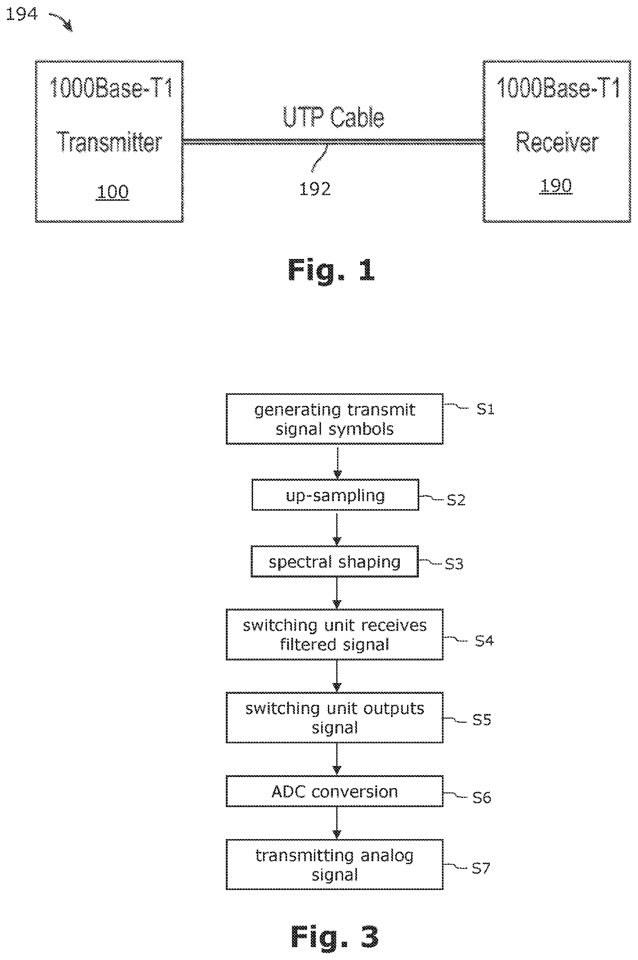
[0053]FIG. 1 shows in a high-level block diagram a communication system 194 with a transmitter device 100. According to the exemplary embodiment described here the communication system 194 is installed in an automotive environment. The transmitter device 100 is communicatively connected with a receiver device 190 being also a component of the communication system 194 via an Unshielded Twisted Pair (UTP) data communication cable 192. The transmitter device 100 is configured for transmitting...


PUM


Abstract

It is described a transmitter device (100) and a method for transmitting an analog signal (251, 261) via an electric cable (192). The transmitter device (100) comprises (a) a signal generation circuit (210) for generating a digital transmit signal (211) comprising a sequence of transmit symbols; (b) a filter circuit (230) for spectrally shaping the generated digital transmit signal (211, 221) and for outputting a filtered digital transmit signal (231); (c) a switching unit (240) comprising (c1) a first input terminal (242) for receiving the filtered digital transmit signal (231), (c2) a second input terminal (244) for receiving another digital transmit signal (297), (c3) an output terminal (246) for outputting a digital transmit output signal (241), wherein the digital transmit output signal (241) is based on, depending on a switching state of the switching unit (240), the filtered digital transmit signal (231) or the another digital transmit signal (297), and (c4) a control terminal (248) for receiving a control signal (285) from a control circuit (280), the control signal (285) being indicative for the switching state. The transmitter device (100) further comprises the control circuit (280); and a digital to analog converter (250) for receiving the digital transmit output signal (241) and for converting the received digital transmit output signal (241) to the analog signal (251, 261).

Description

CROSS-REFERENCE TO RELATED APPLICATIONS[0001]This application claims benefit of U.S. Provisional Application No. 63 / 173,311, filed on Apr. 9, 2021, and European Application No. 21181786.1, filed on Jun. 25, 2021, the entirety of each of which is incorporated herein by reference for all purposes.TECHNICAL FIELD[0002]The present disclosure relates to a transmitter circuit being configured for performing a spectral shaping of radio frequency signals and to a transceiver system comprising such a transmitter circuit. Further, the present disclosure relates to a method for performing a spectral shaping of radio frequency signals to be transmitted.ART BACKGROUND[0003]Automotive vehicles incorporate a large number of electronic circuits. Not only because of the increasing demand for automotive vehicles having the functionality of autonomous driving, it is expected that the trend towards more and more electronic circuits in automotive vehicles will continue. Specifically, this trend is expec...

Claims


Application Information

Patent Timeline
IPC IPC(8): H03F3/24H03F3/217
CPCH03F3/245H03F3/2178H03F2200/451H03F2200/165H04B1/04H04L25/03828H04B2001/0408H04B2001/0416H04L25/0288
Inventor CHINI, AHMADWANG, PEIQINGTAZEBAY, MEHMET VAKIF
Owner AVAGO TECH INT SALES PTE LTD
Features
  • R&D
  • Intellectual Property
  • Life Sciences
  • Materials
  • Tech Scout
  • Unparalleled Data Quality
  • Higher Quality Content
  • 60% Fewer Hallucinations
Learn More