Unlock instant, AI-driven research and patent intelligence for your innovation.

Circuit for downlink/uplink operational mode switching in a TDD wireless communication system

a wireless communication system and operational mode technology, applied in the direction of transmission, gated amplifiers, low noise amplifiers, etc., can solve the problems of high components cost, high cost, and inability to completely shut down the thermal tracking device t within the tx/rx switching time,

Pending Publication Date: 2022-10-27
TEKO TELECOM
View PDF0 Cites 0 Cited by
  • Summary
  • Abstract
  • Description
  • Claims
  • Application Information

AI Technical Summary

Benefits of technology

The present invention provides a circuit for efficient and fast switching from / to DL / UL operational mode in a TDD wireless communication system. The circuit can reduce the overall cost of the used components, reduce the loss in downlink path efficiency, improve system reliability, and reduce power consumption.

Problems solved by technology

In this perspective, one of the main parameters to control is the quiescent current trying to maintain it constant over a large temperature range, which is the real challenging task in this kind of design.
However, the presence of the thermal tracking device T does not allow for complete transistor shut down within Tx / Rx switching time as defined by the 3GPP standard (approximatively 1 μs).
However, several drawbacks are known for the above solution.
A first drawback concerns the high cost of the components.
Particularly, the high cost is due to the high-isolation requirements for the RF switch.
A further drawback concerns the loss in the DL path efficiency.
Particularly, the introduction of an RF switch after the PA increases DL path insertion loss, hence decreasing overall system efficiency.
Furthermore, the know solution has a reduced system reliability.
The reduced reliability is due to the fact that the RF switch deals with high power levels.
Finally, the system realized according to the know solution has high power consumption.

Method used


Image

  • Circuit for downlink/uplink operational mode switching in a TDD wireless communication system
  • Circuit for downlink/uplink operational mode switching in a TDD wireless communication system
  • Circuit for downlink/uplink operational mode switching in a TDD wireless communication system

Examples


embodiments the invention

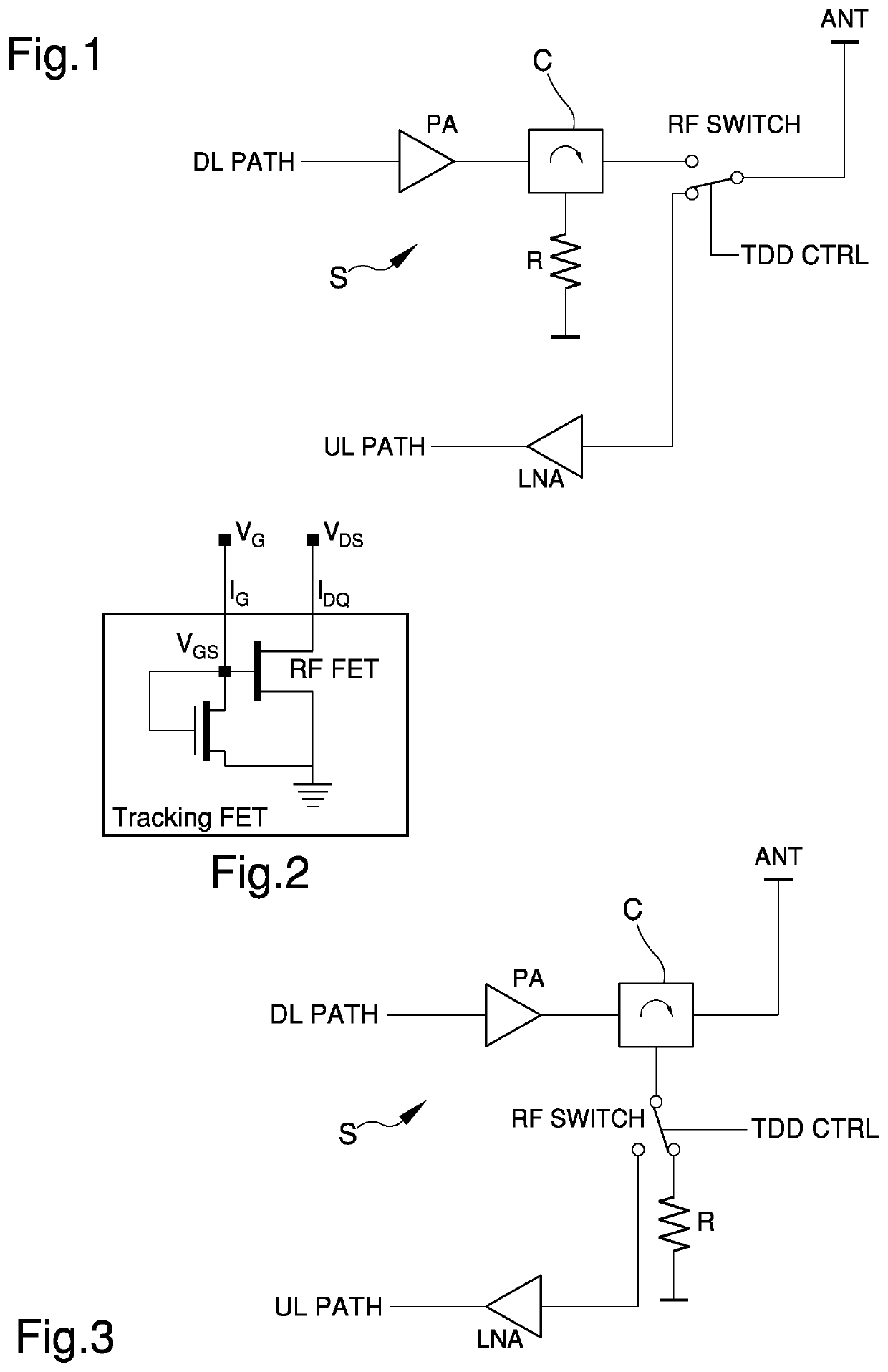
[0029]With particular reference to such illustrations, globally indicated with reference C is a circuit for downlink / uplink operational mode switching in a TDD wireless communication system.

[0030]The circuit C according to the invention allows to remove in a high-level TDD RF front end the RF switch at the antenna port and place it in the UL path before LNA, as shown in FIG. 3, hence addressing all issues of the known solutions.

[0031]Particularly, the circuit C is designed to act on the power amplifier LDMOS FET Gate voltage, while the Drain voltage is maintained constant.

[0032]From a high-level viewpoint, the circuit C according to the invention comprises:[0033]a voltage generator for setting the quiescent Drain current of the power amplifier LDMOS;[0034]a large-value resistor connected in series to the voltage generator;[0035]a sample-and-hold circuit comprising two analog switches driven by the synchronism signal of the TDD standard and a hold capacitor.

[0036]This circuit C allow...


PUM


Abstract

A circuit for downlink / uplink operational mode switching in a TDD wireless communication system comprises a field-effect transistor operatively connected to a power amplifier on the downlink path of a RF front-end apparatus in a TDD wireless communication system, a first voltage generator connected to a large-value first resistor, a second voltage generator connected to a second resistor, a large-value hold capacitor, and a sample-and-hold circuit configured to be switched between a reception configuration, wherein the first voltage generator is connected to the gate of the field-effect transistor and the large-value capacitor is connected to the first voltage generator through the first resistor, and a transmission configuration, wherein the gate of the field-effect transistor is connected to the hold capacitor and the hold capacitor is connected to the second voltage generator through the second resistor.

Description

TECHNICAL FIELD[0001]The present invention relates to a circuit for downlink / uplink operational mode switching in a TDD wireless communication system.BACKGROUND ART[0002]In the field of telecommunications, it is known that an efficient and fast switching from / to DL / UL (downlink / uplink) operational mode, i.e. Tx / Rx (transmission / reception), is of outmost importance when dealing with Time Division Duplexed (TDD) signals.[0003]Particularly, when the system is in Tx mode a PA (Power Amplifier) on the DL should be turned on and this can be realized by deploying an LDMOS transistor equipped with an embedded thermal tracking device for thermal compensation. An example of high-level standard TDD RF front end designed with and high-isolation RF switch at the antenna port is showed in FIG. 1.[0004]Particularly, it is known that during a RF power amplifier design phase, an important aspect to be considered is performance variation over temperature. In this perspective, one of the main paramete...

Claims


Application Information

Patent Timeline
Patent Type & Authority Applications(United States)
IPC IPC(8): H03F3/193H03F1/30H03F3/24H03F3/72H04B1/48
CPCH03F3/193H03F1/301H03F3/245H03F3/72H04B1/48H03F2200/294H03F2200/451H03F2203/7206
Inventor DURANTE, DAVIDENOTARGIACOMO, MASSIMO
Owner TEKO TELECOM