
Multijunction solar cell

a solar cell and multi-junction technology, applied in the field of solar cells and the fabrication of solar cells, can solve the problems of reducing the efficiency of photon conversion at the sub-cell, the overall efficiency of the solar cell, and the tensile complexity of the manufactur

Pending Publication Date: 2022-11-03
SOLAERO TECH CORP BY ROCKET LAB
View PDF9 Cites 0 Cited by
  • Summary
  • Abstract
  • Description
  • Claims
  • Application Information

AI Technical Summary

Benefits of technology

The present invention aims to enhance the performance of a multijunction solar cell by optimizing the composition of the window layer, which is placed at the top of the solar subcell. This will increase the amount of sunlight that can be captured and converted into electrical energy. Additionally, a portion of the thickness of the window layer can be oxidized to further improve the efficiency of the solar cell.

Problems solved by technology

Compared to silicon, III-V compound semiconductor multijunction devices have greater energy conversion efficiencies and generally more radiation resistance, although they tend to be more complex to manufacture.
In some embodiments, the window layer may have a higher band gap than the adjacent emitter layer, with the higher band gap tending to suppress minority-carrier injection into the window layer, and as a result tending to reduce the recombination of electron-hole pairs that would otherwise occur in the window layer, thereby decreasing the efficiency of photon conversion at that subcell, and thus the overall efficiency of the solar cell.
However, the specific composition of the window layer and the oxidation process taught therein are quite restricted and limited, and the resulting manufacturability and the quantum efficiency associated with such prior art is demonstrably highly unsatisfactory from a commercial perspective.

Method used


Image

  • Multijunction solar cell
  • Multijunction solar cell
  • Multijunction solar cell

Examples


first embodiment

[0203]FIG. 3 is a highly simplified perspective view of a space vehicle incorporating a photoelectric power system according to the present disclosure. The space vehicle 500 includes a plurality of foldable substantially rectangular panels 501, 502, 503, 504, etc. which extend from the vehicle to form “wings”.

second embodiment

[0204]FIG. 4 is a highly simplified perspective view of a space vehicle incorporating a photoelectric power system with roll-out deployment according to the present disclosure. In this embodiment, the space vehicle 2000 incorporates a solar cell array 2004 mounted on a deployable flexible sheet 2003 in which the solar cell array 2004 incorporates the solar cells or solar cell modules according to the present disclosure.

[0205]The sheet 2003 may wrap around a mandrel 2002 prior to being deployed in space. One of the advantages of such an arrangement is that the storage volume in the launch vehicle for the solar cell array is relatively low, thereby enabling either an increased payload size or a smaller volume launch vehicle requirement. The space vehicle 2000 includes a payload 2005 which is powered by the array of solar cell assemblies 2004.

[0206]FIG. 5 is a graph representing the band gap at certain binary material and their lattice constants. The band gap and lattice constants of t...


PUM


Abstract

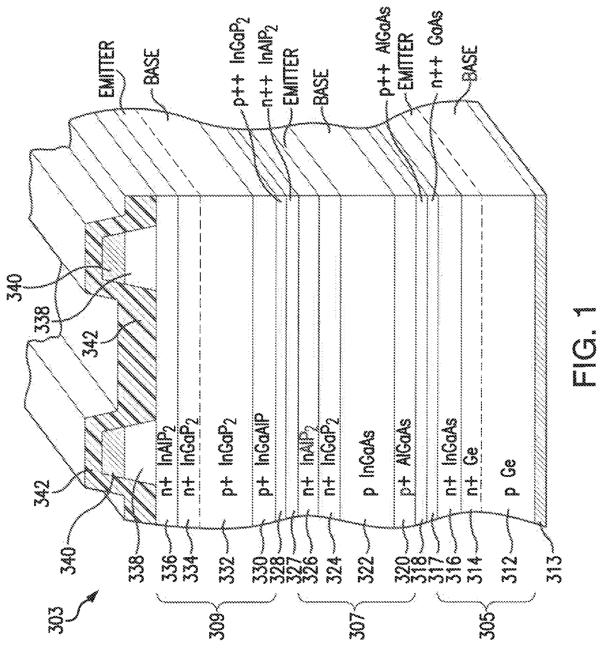
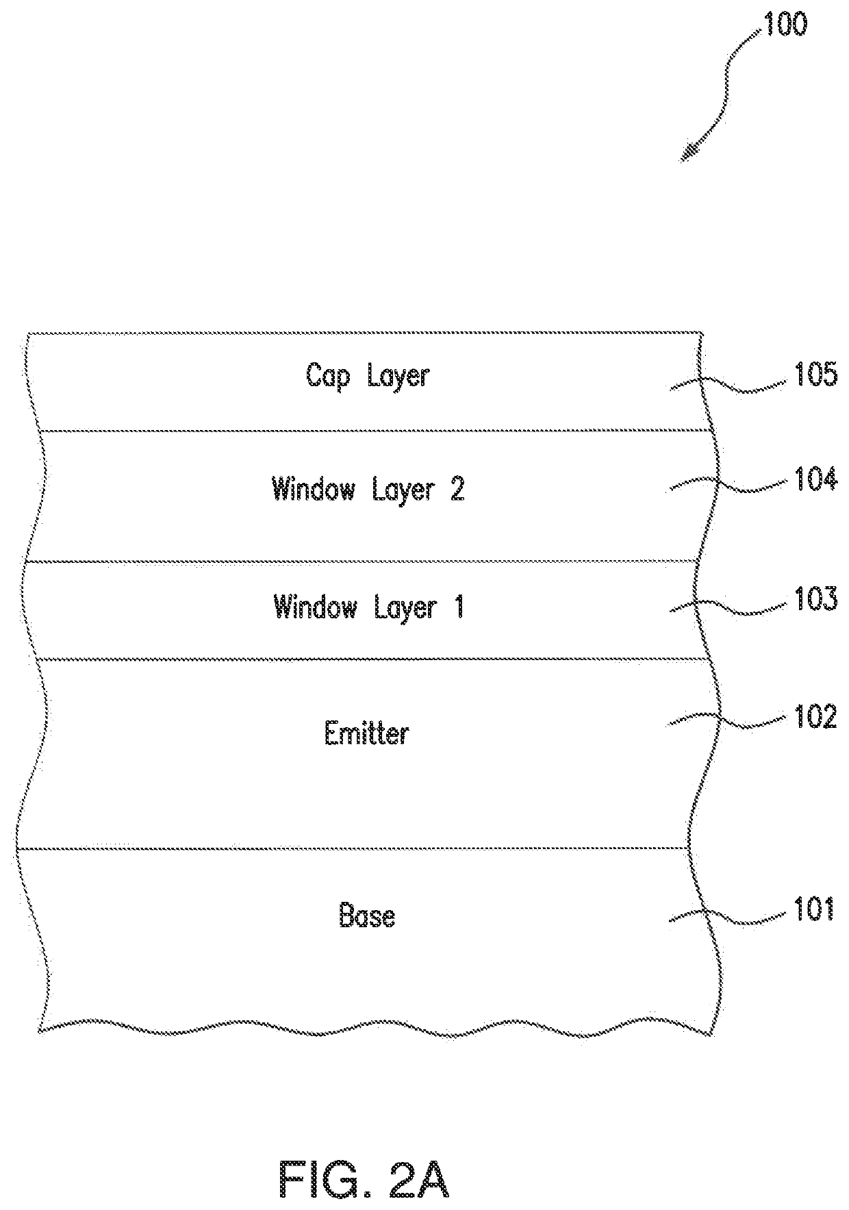
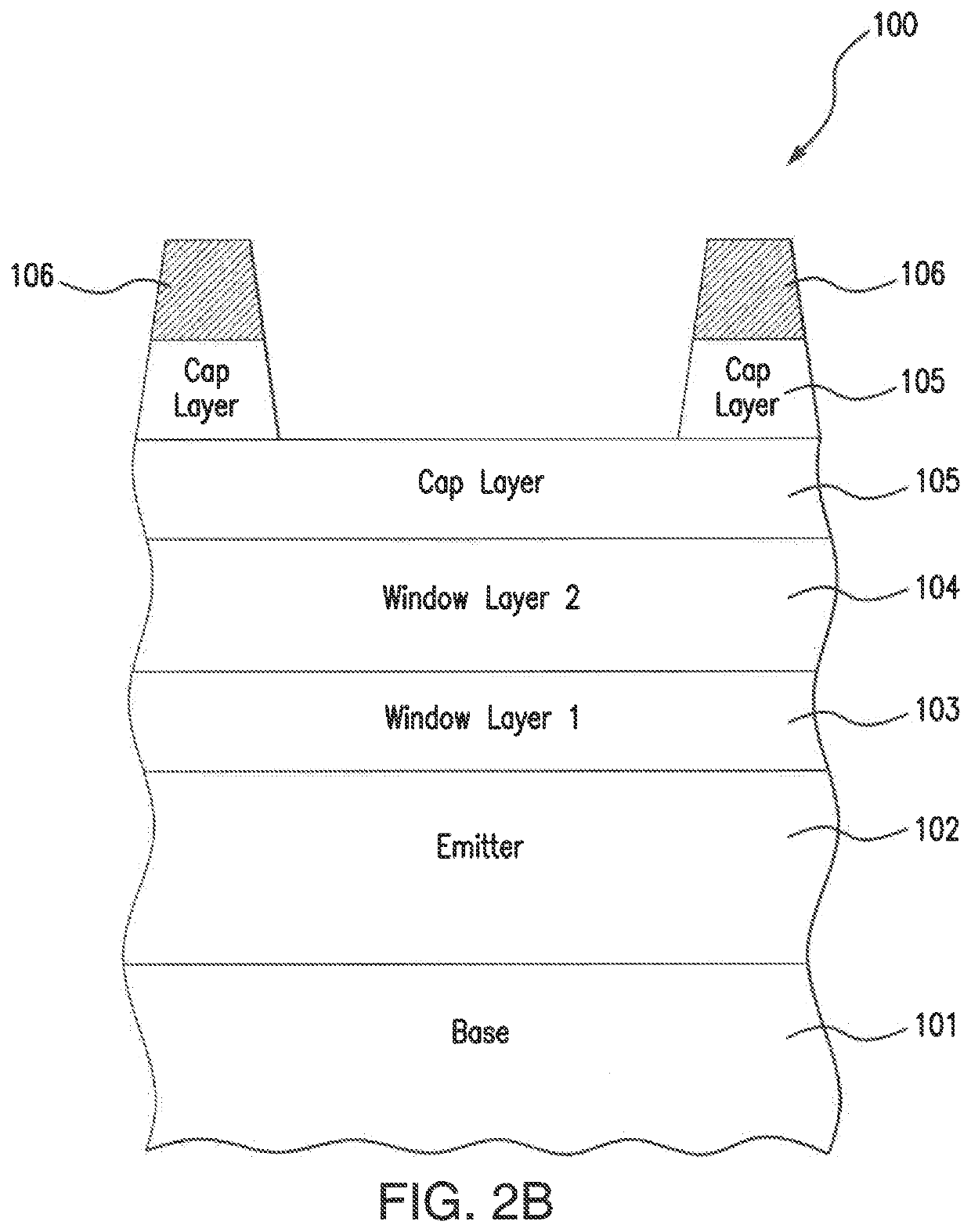
A multijunction solar cell including a substrate and a top (or light-facing) solar subcell having an emitter layer, a base layer, and a window layer adjacent to the emitter layer, the window layer composed of a material that is optically transparent, has a band gap of greater than 2.6 eV, and includes an appropriately arranged multilayer antireflection coating on the top surface thereof.

Description

REFERENCES TO RELATED APPLICATIONS[0001]The present application claims benefit of U.S. Provisional Application Ser. No. 63 / 181,484 filed Apr. 29,2021.[0002]The present application is related to U.S. patent application Ser. No. 15 / 464,651 filed Mar. 10, 2017, now U.S. Pat. No. 10,910,506 hereby incorporated by reference.BACKGROUND1. Field of the Invention[0003]The present disclosure relates to solar cells and the fabrication of solar cells, and more particularly the design and specification of the window layer in the top solar subcell, and the antireflective coating layer, in multijunction solar cells based on III-V semiconductor compounds.2. Description of the Related Art[0004]Solar power from photovoltaic cells, also called solar cells, has been predominantly provided by silicon semiconductor technology. In the past several years, however, high-volume manufacturing of III-V compound semiconductor multijunction solar cells for space applications has accelerated the development of su...

Claims


Application Information

Patent Timeline
IPC IPC(8): H01L31/065H01L31/054H01L31/0725H01L31/0735H01L31/18
CPCH01L31/065H01L31/0547H01L31/0725H01L31/0735H01L31/1844H01L31/1852B64G1/443B64G1/222H01L31/078H01L31/184H01L31/02167H01L31/186H01L31/0549Y02E10/544H01L31/0687
Inventor DERKACS, DANIELESPENLAUB, ANDREW COLIN
Owner SOLAERO TECH CORP BY ROCKET LAB
Learn More