
Llc converter circuit

a converter circuit and converter technology, applied in the field of converters, can solve the problems of slow response speed and insufficient bandwidth, and achieve the effect of reducing the number of circuits

Pending Publication Date: 2022-11-03
POWER FOREST TECH
View PDF7 Cites 0 Cited by
  • Summary
  • Abstract
  • Description
  • Claims
  • Application Information

AI Technical Summary

Benefits of technology

The patent text describes an LLC converter circuit that improves response speed and bandwidth by controlling the conduction state of the half-bridge switch circuit based on sensing voltage. The control circuit provides two control signals based on the sensing voltage, which effectively controls the on / off switching of the half-bridge switch circuit. This results in improved performance of the LLC converter circuit.

Problems solved by technology

However, in a general LLC converter, since the feedback control is performed by sending a signal output from a secondary side of the transformer back to a primary side of the transformer via an optocoupler, problems such as slow response speed and insufficient bandwidth may occur.

Method used


Image

  • Llc converter circuit
  • Llc converter circuit
  • Llc converter circuit

Examples


Embodiment Construction

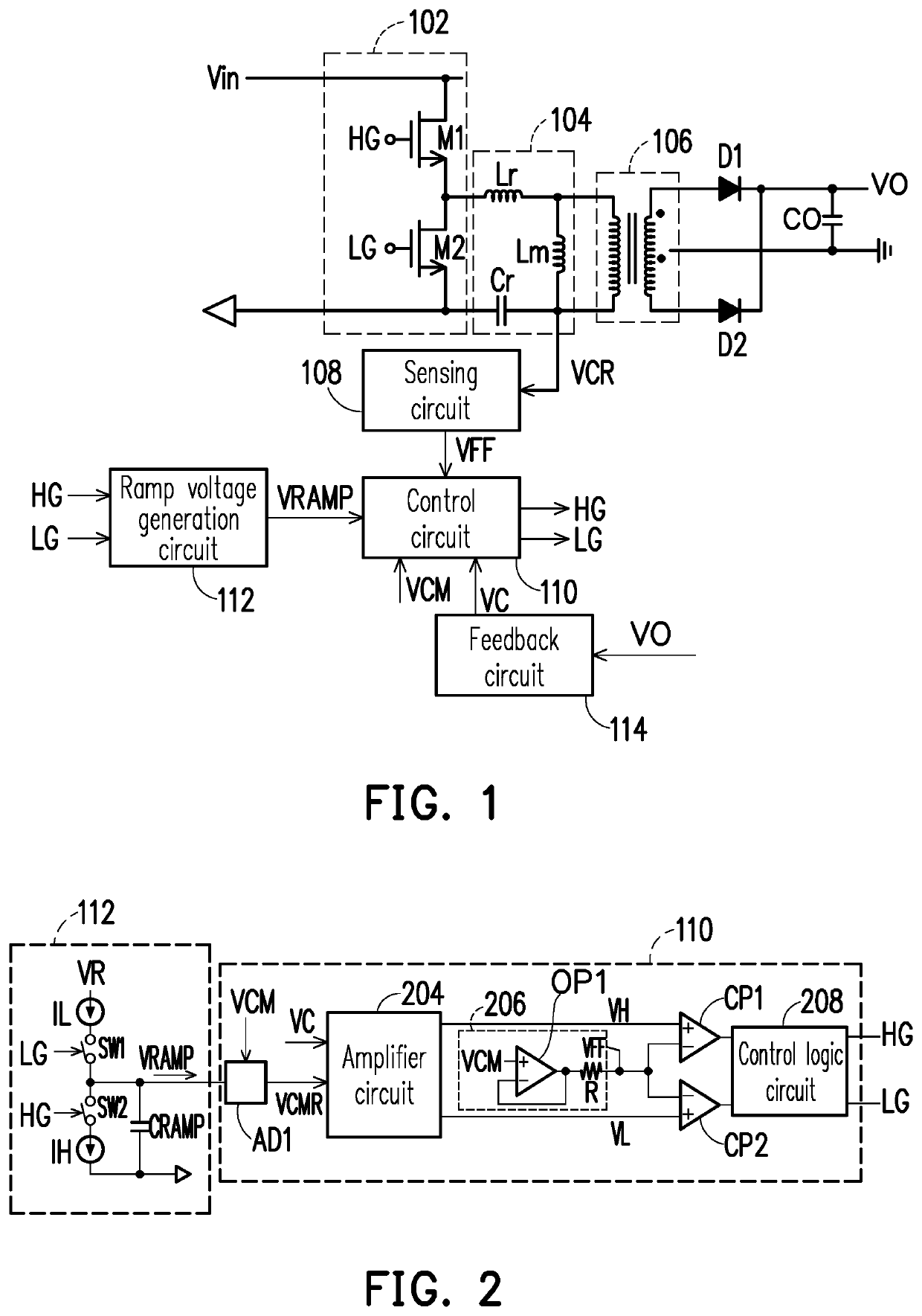
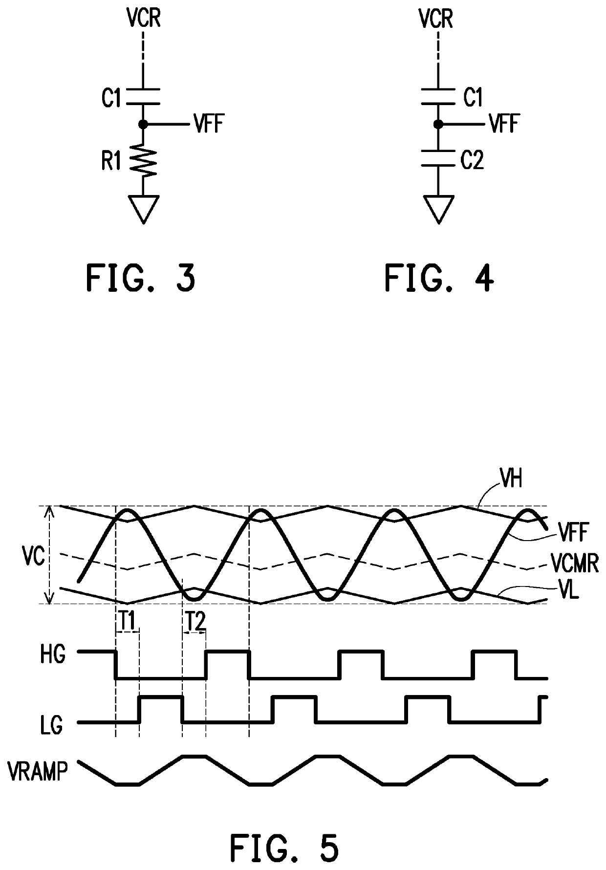
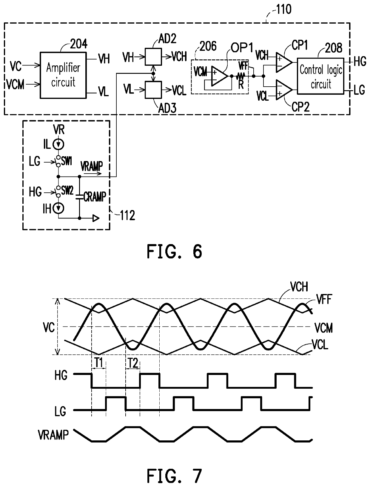
[0029]FIG. 1 is a schematic diagram of an LLC converter circuit according to an embodiment of the disclosure. Please refer to FIG. 1. The LLC converter circuit may include a half-bridge switch circuit 102, a resonant network 104, a transformer 106, a sensing circuit 108, a control circuit 110, a ramp voltage generation circuit 112, and a feedback circuit 114. The resonant network 104 is coupled to the half-bridge switch circuit 102, the transformer 106, and the sensing circuit 108. The transformer 106 may be coupled to an output terminal of the half-bridge switch circuit 102 via a rectifier diode D1, a rectifier diode D2 and an output capacitor CO. The control circuit 110 is coupled to the sensing circuit 108 and the ramp voltage generation circuit 112. The feedback circuit 114 is coupled between an output terminal of the LLC converter circuit and the control circuit 110.

[0030]Specifically, the half-bridge switch circuit 102 has a first input terminal and a second input terminal. In...


PUM


Abstract

An LLC converter circuit is provided. A control circuit provides a first control signal and a second control signal according to a sensing voltage generated by sensing a voltage on a resonant capacitor of a primary side, so as to control a conduction state of a half-bridge switch circuit.

Description

CROSS-REFERENCE TO RELATED APPLICATION[0001]This application claims the priority benefit of Taiwan application serial no. 110115301, filed on Apr. 28, 2021. The entirety of the above-mentioned patent application is hereby incorporated by reference herein and made a part of this specification.BACKGROUNDTechnical Field[0002]The disclosure relates to a converter, and particularly relates to an LLC converter circuit.Related Art[0003]An LLC converter is a DC / DC converter that includes an LLC resonant circuit composed of a leakage inductance and a magnetizing inductance of a transformer and a capacitor, a signal generation circuit (such as a half-bridge circuit) generating a square wave shaped voltage signal supplied to the LLC resonant circuit, and a rectifier circuit rectifying an output of the transformer.[0004]In the LLC converter, in order to reduce variation in an output voltage during a load change, the output voltage or the like is used for feedback control of a switching frequenc...

Claims


Application Information

Patent Timeline
IPC IPC(8): H02M3/337H02M1/00H02M3/335
CPCH02M3/3376H02M1/0022H02M3/33507Y02B70/10H02M3/01H02M3/33571
Inventor CHIU, CHAO-CHANGKUAN, CHIEN-WEI
Owner POWER FOREST TECH
Learn More