
A power supply device, a power receiving device and power supply and receipt methods

Pending Publication Date: 2022-11-10
SIGNIFY HLDG BV
View PDF0 Cites 0 Cited by
  • Summary
  • Abstract
  • Description
  • Claims
  • Application Information

AI Technical Summary

Benefits of technology

The invention is a device that can transmit and receive power over a communication bus using a protocol where a signal level is encoded by shorting two lines. This allows for continuous power harvesting. The device can also switch between different communication protocols, and can bypass a current limiter circuit to reduce standby power consumption or maintain additional functions. The device can adjust settings to reduce power demand if voltage drops while the bypass unit is active. Overall, the invention enables efficient power transmission and utilization in a communication system.

Problems solved by technology

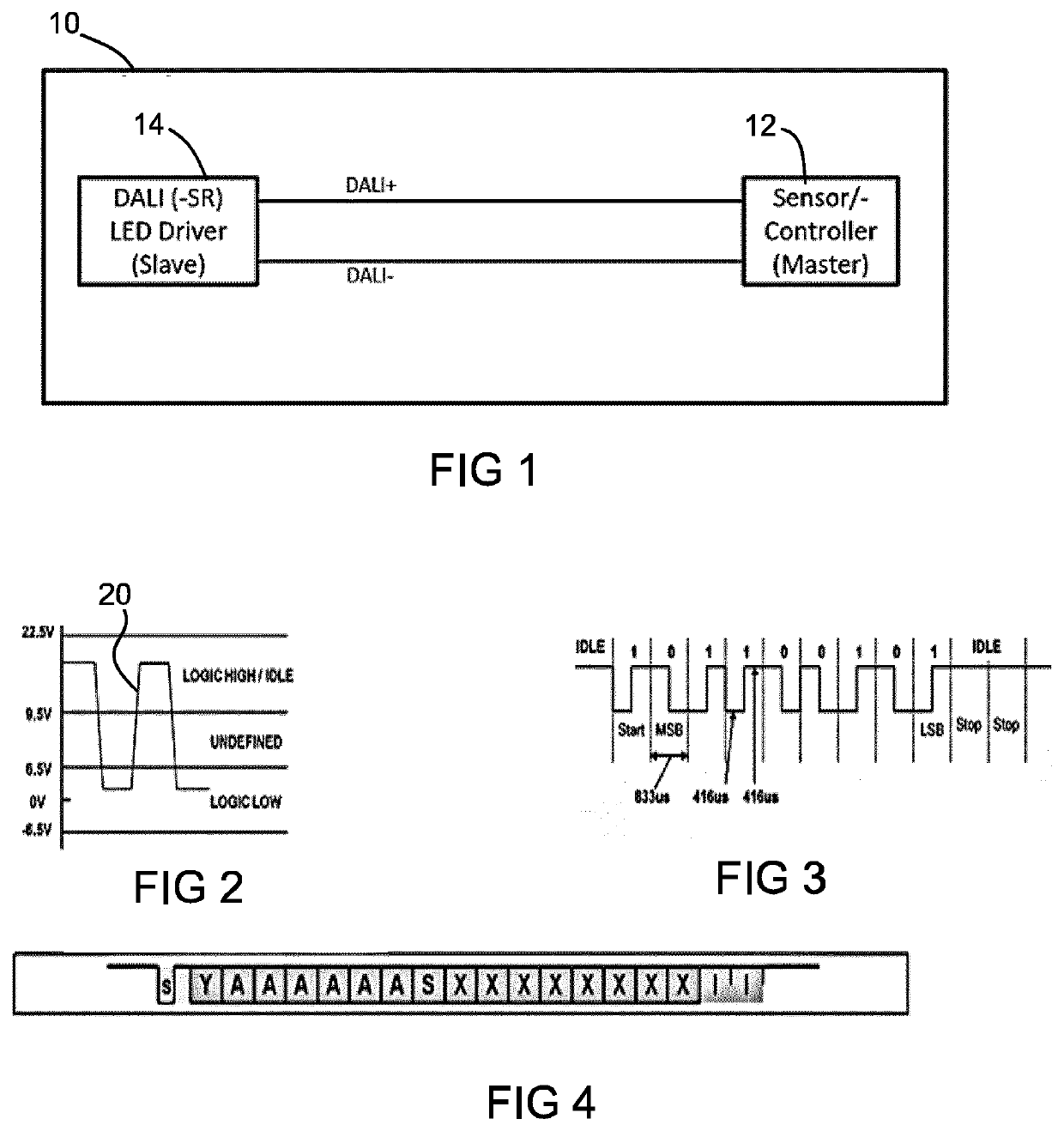
One of the challenges with delivering power this way originates from the DALI signaling scheme.
Another challenge with delivering power this way is to enable the lowest possible standby mode in the power receiving device and / or to enable the maximum of functionality in a low power standby mode.

Method used


Image

  • A power supply device, a power receiving device and power supply and receipt methods
  • A power supply device, a power receiving device and power supply and receipt methods
  • A power supply device, a power receiving device and power supply and receipt methods

Examples


Embodiment Construction

[0084]The invention will be described with reference to the Figures.

[0085]It should be understood that the detailed description and specific examples, while indicating exemplary embodiments of the apparatus, systems and methods, are intended for purposes of illustration only and are not intended to limit the scope of the invention. These and other features, aspects, and advantages of the apparatus, systems and methods of the present invention will become better understood from the following description, appended claims, and accompanying drawings. It should be understood that the Figures are merely schematic and are not drawn to scale. It should also be understood that the same reference numerals are used throughout the Figures to indicate the same or similar parts.

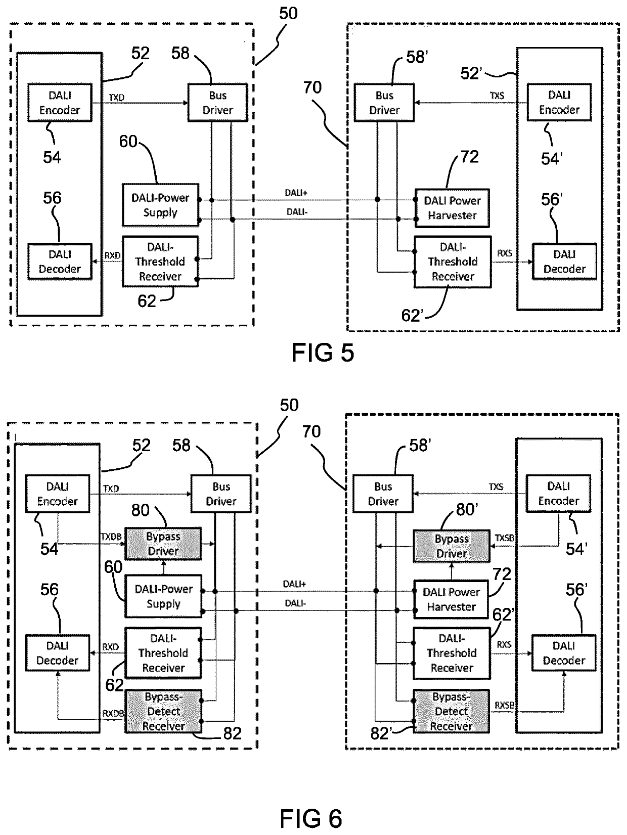
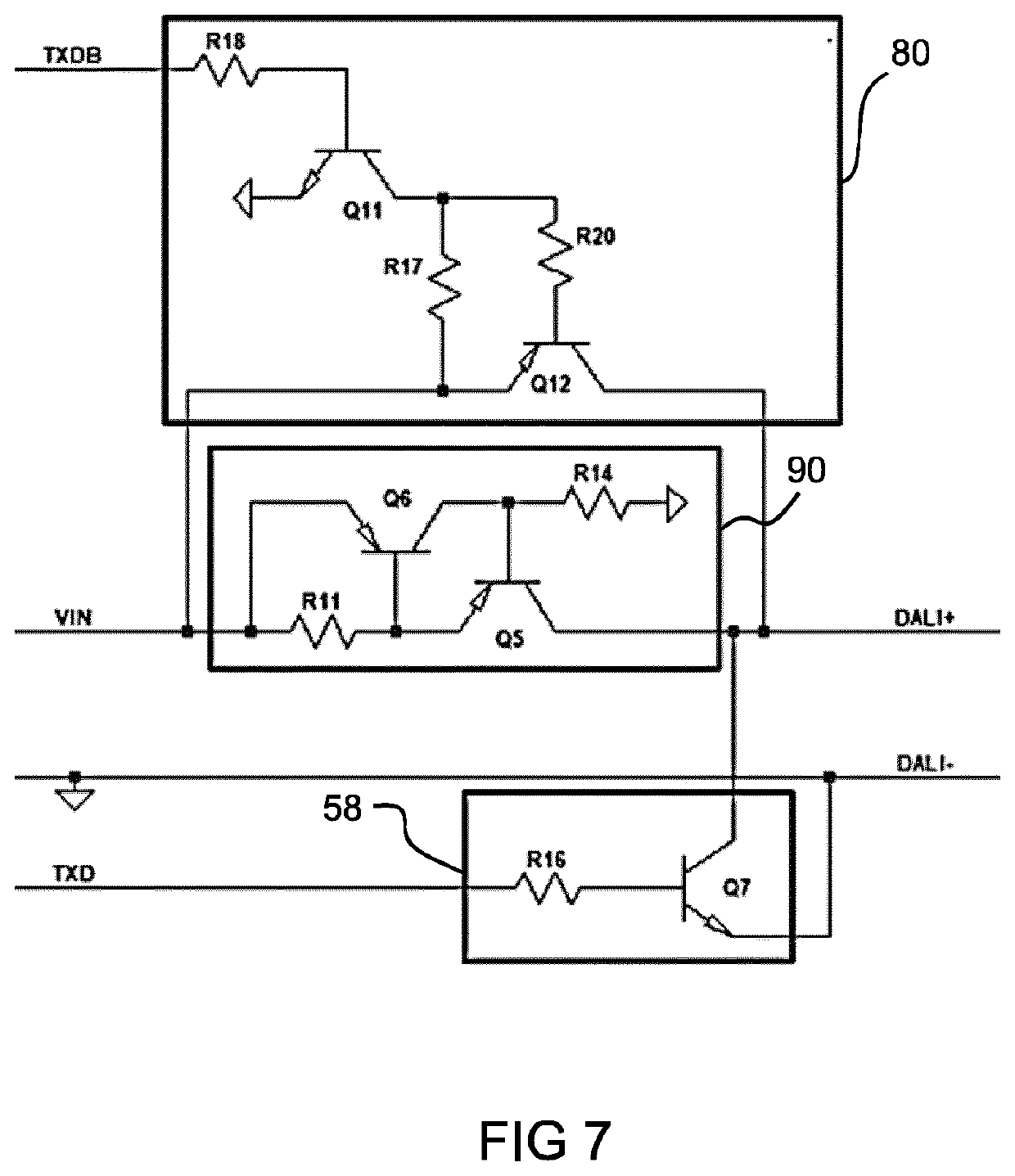
[0086]The invention provides a device which is adapted to transmitting power to, or receive power from, a remote device over first and second communication lines and to communicate with the remote device over the first and...


PUM


Abstract

In one aspect, a device is adapted to transmitting power to, or receive power from, a remote device over first and second communication lines (DALI+, DALI−) and to communicate with the remote device over the first and second communication lines. A first driver implements a first communications protocol which comprises coupling the first and second communication lines together to encode a first signal level and isolating the first and second communication lines from each other to encode a second signal level. This may be a DALI protocol. A second driver implements a second communications protocol which comprises modulating the first communication line with a signal having a low modulation depth. The second communications protocol means there is always a voltage difference between the two communication lines to enable continuous power harvesting. A second aspect relates to efficient power transfer by disabling a current limiter function, when possible.

Description

FIELD OF THE INVENTION[0001]This invention relates to a power supply device, a power receiving device and power supply and receipt methods, in particular for powering devices over communication lines.BACKGROUND OF THE INVENTION[0002]Powering devices over communication lines of a communications bus is a known approach. One example is the powering of sensors using a DALI bus, within a lighting infrastructure. The deployment of sensors integrated in luminaires and powered by power supplies integrated with the LED driver is becoming an accepted technical solution. This exploits the full potential of Internet of Things (IoT) in the lighting domain.[0003]By way of example, the applicant has introduced a so-called sensor ready extension to the basic DALI signaling technology. Drivers equipped with this technology can provide power to luminaire-integrated or ceiling-integrated sensors.[0004]One of the challenges with delivering power this way originates from the DALI signaling scheme. This ...

Claims


Application Information

Patent Timeline
IPC IPC(8): H05B47/185
CPCH05B47/185H05B47/18
Inventor ABBO, ANTENEH ALEMUDE JONGH, FRITS TOBIBEIJ, MARCELWERNARS, JOHANNES PETRUS
Owner SIGNIFY HLDG BV
Learn More