Airflow rate regulating device

a technology of airflow rate and regulating device, which is applied in water supply installation, process and machine control, instruments, etc., can solve the problems of inability of the system to react quickly, drawbacks of traditional air filtration system, and electric actuators

Inactive Publication Date: 2000-01-04
LES SYST & PROCEDES DYNAPHARM
View PDF8 Cites 19 Cited by
  • Summary
  • Abstract
  • Description
  • Claims
  • Application Information

AI Technical Summary

Benefits of technology

to provide an improved airflow rate regulating device that alleviates at...

Problems solved by technology

Traditional air filtration systems have drawbacks.
Perhaps, the most acute one is the inability of the system to react rapidly enough to air pressure variations in the space (occurring wh...

Method used


Image

  • Airflow rate regulating device
  • Airflow rate regulating device
  • Airflow rate regulating device

Examples


Embodiment Construction

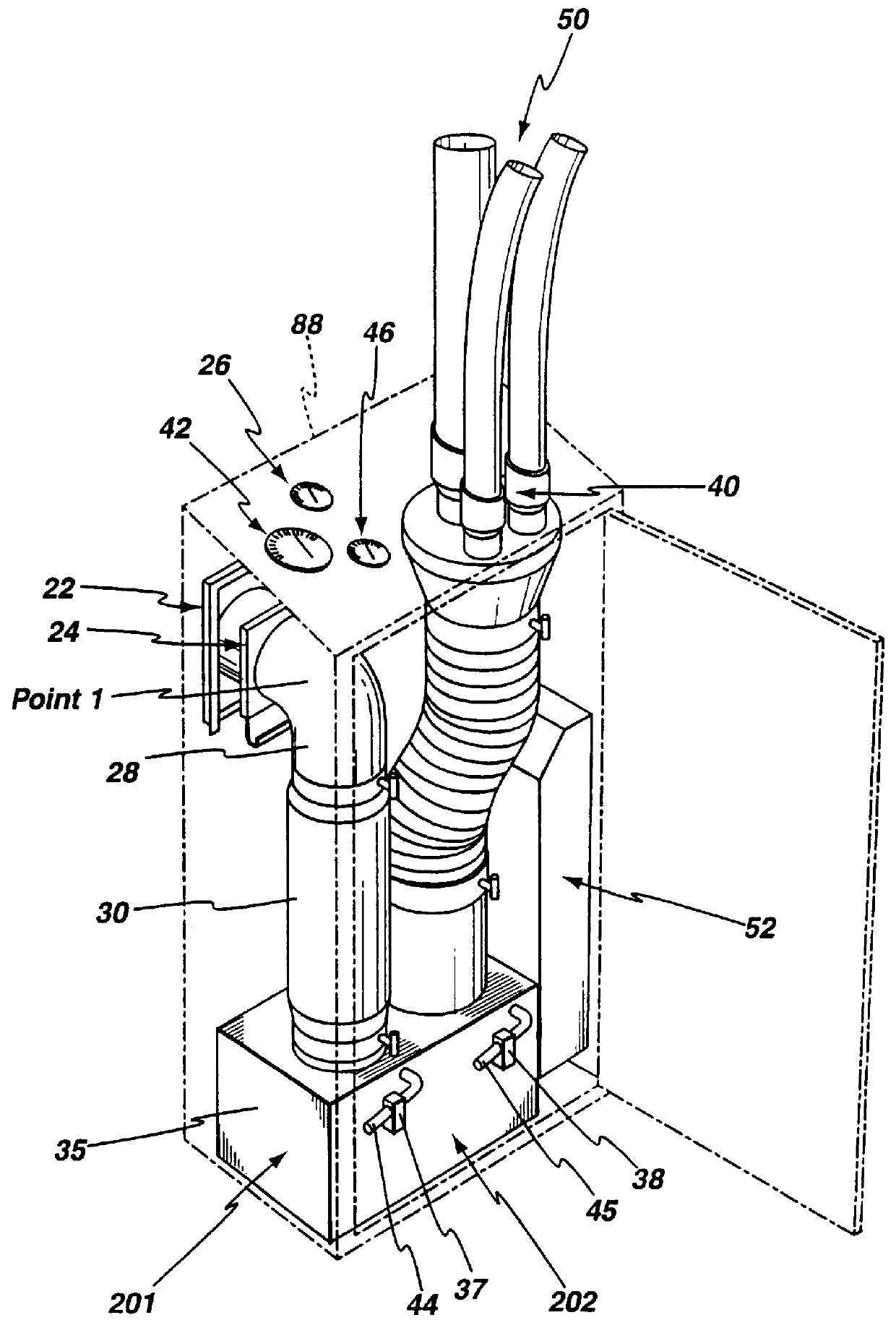
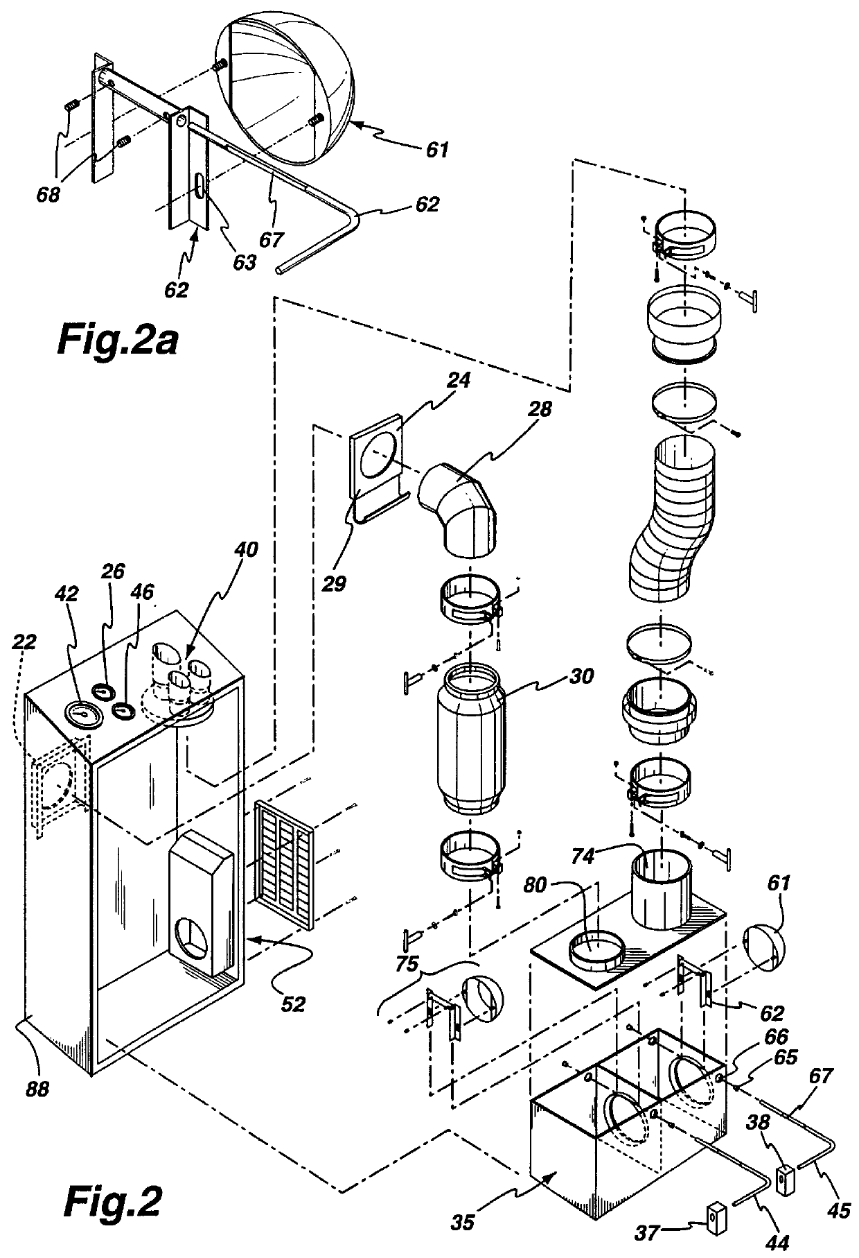
FIGS. 1 and 2 of the drawings illustrate the airflow rate regulating device constructed in accordance with the preferred embodiment of the invention. The airflow rate regulating device 35 is mounted in a suitable cabinet 88 and it is connected to a vacuum source at central inlet 22 of the cabinet 88 through elbow 28 and conduit 30. Typically, the airflow rate regulating device 35 is integrated in an air filtration system and the vacuum source is a fan unit or a suitable pump designed to transport air through the filtration system. A negative pressure is established at the main port 80 of the airflow rate regulating device 35 by the vacuum source. A sliding gate valve 24 located immediately next to the central inlet 22 allows an operator to set the initial vacuum pressure at the main port 80 of the airflow rate regulating device 35 by adjusting the opening of the sliding valve 24.

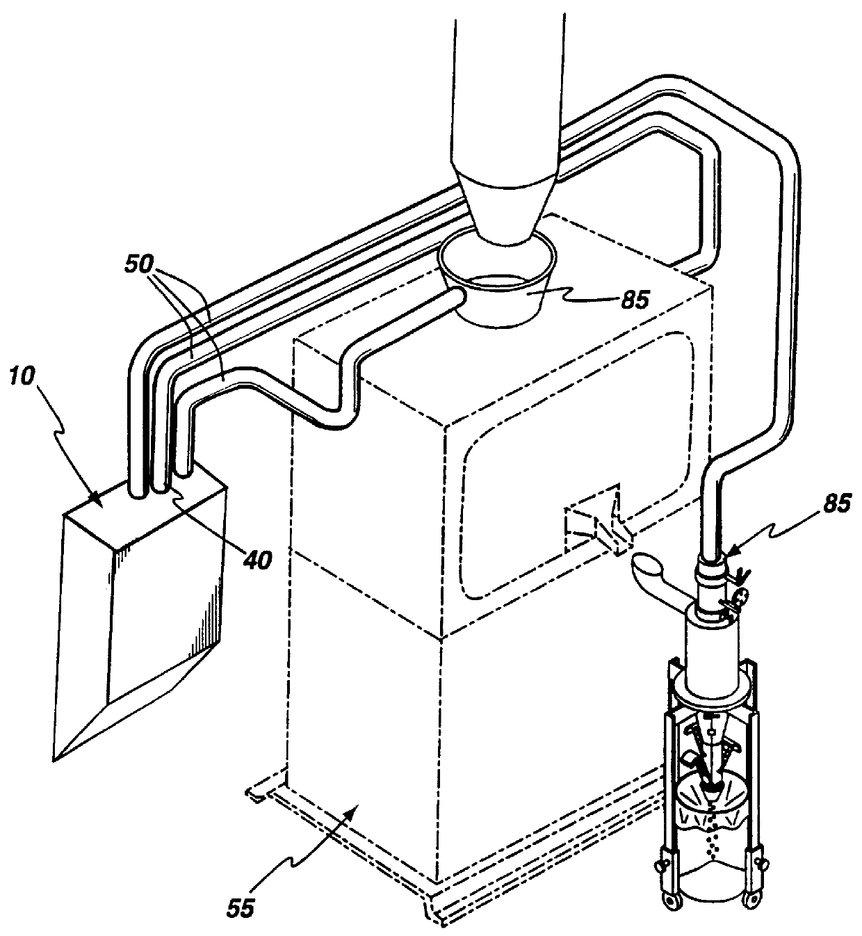
FIG. 3 illustrates a typical unit installed in a controlled room. The flexible hoses 50 are coupled to ou...


PUM


Abstract

An airflow rate regulating device which is installed in a vacuum unit that collects contaminants from a processing station in a controlled space. This device enables a vacuum unit to maintain a continuous suction of contaminant particles from a processing station when there are pressure variations in the controlled space. The airflow rate regulating device is mounted in a suitable cabinet 88 and connected to a vacuum source. The airflow rate regulating device has a casing divided into two chambers separated by a wall having an passageway through which air flows from one chamber to the next. Each chamber features an airflow rate regulation valve comprising a movable member extending across the flow of air passing through the casing, that can be adjusted using counterweights. When a pressure disturbance occurs in the controlled room from a door opening, or when a hose leading the contaminant source is disconnected, the airflow rate regulation valves react to maintain sufficient vacuum pressure at the contaminants source. Since the airflow rate regulating device is mechanical, its response time to pressure is nearly instantaneous.

Description

The present invention relates to the art of airflow regulation devices. In particular, the invention finds applications in airflow rate control devices that may be typically used in enclosures to provide a source of suction to a processing station and at the same time assist in maintaining the enclosure at a negative pressure relative to an adjacent room. Such installations are usually found in pharmaceutical plants where it is essential to avoid chemical substances being released outside a certain enclosure.In many applications, it is desirable to control the air pressure within a space such as in so called <<clean rooms>> used in laboratories, biotech, biomedical, hospital, cosmetic, food processing, research center, semiconductor industries, etc . . . . For instance, pharmaceutical installations that produce medicinal tablets are required by regulation to confine the tablet manufacturing equipment within a closed space and provide an air filtration system capable of e...

Claims


Application Information

Patent Timeline
IPC IPC(8): G05D7/01G05D7/00
CPCG05D7/0173Y10S137/907Y10T137/2572Y10T137/7903Y10T137/88054
Inventor TRUSSART, MICHEL
Owner LES SYST & PROCEDES DYNAPHARM
Why Eureka
Try Eureka