Ultra-fast configuration mode for a programmable logic device

a programmable logic and configuration mode technology, applied in the direction of pulse technique, computation using denominational number representation, instruments, etc., can solve the problems of occupying excessive requiring substantial numbers of conductors, and shifting register approach to programming may take up too much space and other resources, so as to increase the potential for reducing loading time and reducing load tim

Inactive Publication Date: 2000-01-04
ALTERA CORP
View PDF6 Cites 27 Cited by
  • Summary
  • Abstract
  • Description
  • Claims
  • Application Information

AI Technical Summary

Benefits of technology

It will be apparent that the above-described methods and apparatus eliminate the need to wait for data to reach its targeted programmable element before introducing data targeted for other programmable elements into the series. Where n is the number of programmable elements in the series, and tee is the time required to load data into a programmable element, use of the inventive concepts can reduce loading time from a number on the order of n.sup.2 t.sub.ee, to a number on the order of 2nt.sub.ee (where a data value is moved only as far as the next programmable element in each substep of a two substep implementation). The larger the n, the greater the potential reduction in loading time as the square of n (n.sup.2) rapidly outpaces the doubling of n (2n) as n increases.

Problems solved by technology

A disadvantage of this approach is that shift registers are relatively complex and require substantial numbers of conductors for interstage data transfer, clocking, etc.
Thus in complex logic circuit structures, the shift register approach to programming may take up excessive space and other resources, and may even become a limiting factor in the design of the device.
The testing of shift register programmed devices is also relatively cumbersome because the shift register can only be tested by shifting data all the way through it.
If, as is common in very complex logic circuits, the shift registers are long, it may take a relatively long time to shift test data through them.
The time it takes data to pass through all the upstream programmable elements adds to the total time required to program the device and amounts to an unproductive delay.

Method used


Image

  • Ultra-fast configuration mode for a programmable logic device
  • Ultra-fast configuration mode for a programmable logic device
  • Ultra-fast configuration mode for a programmable logic device

Examples


Embodiment Construction

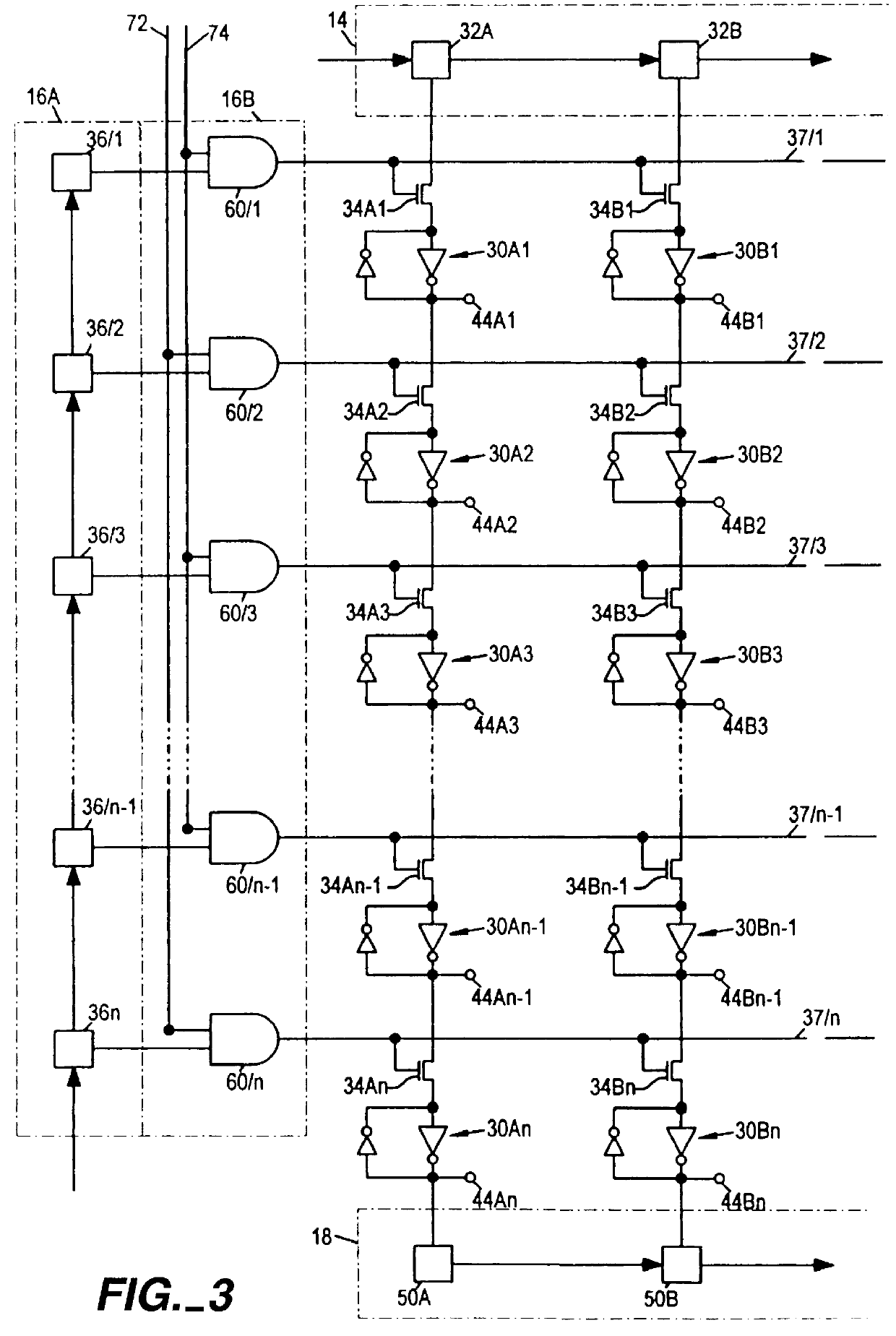
FIG. 4 is a pictorial representation of the loading process described in reference to FIG. 3. In order not to obscure an understanding of the invention with unnecessary detail, the example depicted in FIG. 4 shows the loading of a single series of programmable elements comprised of only 6 elements (n=6), with data values shown as a, b, c, d, e, and f loaded into programmable elements 1, 2, 3, 4, 5, and 6, respectively. A bar appearing over the top of an a, b, c, d, e, or f value indicates the complement of that value. Twelve successive time periods are shown as vertical segments of FIG. 4 and designated t.sub.0 -t.sub.11. Time period t.sub.0 represents a pre-load state of the device. Time period t.sub.11 represents the time period wherein the final input data item reaches the programmable element targeted for its storage. Each time period t.sub.1 -t.sub.11 represents a time period used to perform a single substep operation. A first row of boxes, designated DRE A, shows the content o...


PUM


Abstract

In order to speed loading of a programming structure wherein the programmable elements in a cellular programmable logic integrated circuit (such as a field programmable gate array ("FPGA") or a programmable logic device ("PLD")) are connected in one or more series with switches interposed between elements in the series, switches are enabled and disabled in a systematic pattern to "walk" data from the data source to a targeted programmable element. When a programmable element stores its targeted data, the switch associated with the programmable element is thereafter disabled to prevent changes in the stored data. Incrementally moving data through the series of programmable elements permits the series to reliably carry multiple data items concurrently, thereby speeding the loading process.

Description

1. Field of the InventionThis invention relates to methods and apparatus for programming programmable logic integrated circuits such as field programmable gate arrays ("FPGAs") and many kinds of programmable logic devices ("PLDs").2. Description of Related ArtExtremely powerful and flexible programmable logic circuit architectures are known as shown, for example, by Pedersen U.S. Pat. No. 5,260,610 and Cliff U.S. Pat. No. 5,260,611, both of which are hereby incorporated by reference herein. These architectures include large numbers of logic modules, each of which is programmable to perform any of several relatively elementary logic functions. An extensive network of conductors is provided for programmably interconnecting these logic modules in order to provide much more complex logic functions. These logic circuits include very large numbers of programmable elements. Each logic module has a substantial number of these elements, and the interconnection network also requires many such...

Claims


Application Information

Patent Timeline
Patent Type & Authority Patents(United States)
IPC IPC(8): H03K19/177
CPCH03K19/17776H03K19/17758
Inventor VEENSTRA, KERRY
Owner ALTERA CORP
Why Eureka
Try Eureka