Manufacturing method of R-Fe-B sintered magnet

A technology of sintered magnets and manufacturing methods, which is applied in the direction of inductance/transformer/magnet manufacturing, magnetic objects, magnetic materials, etc., can solve the problems of reduced loading, waste of magnets, increased workload, etc. Loading time, effect of reducing spacing

Active Publication Date: 2014-03-19
YANTAI ZHENGHAI MAGNETIC MATERIAL CO LTD
View PDF8 Cites 25 Cited by
  • Summary
  • Abstract
  • Description
  • Claims
  • Application Information

AI Technical Summary

Problems solved by technology

[0003] At present, various methods have been proposed to achieve the effect of grain boundary diffusion, which can be roughly classified into two categories: one is the contact method, which arranges heavy rare earth elements on the surface of the magnet, and then sinters the heavy rare earth elements along the grain boundary through long-term low-temperature sintering. boundary infiltration to achieve grain boundary diffusion (refer to Patent Document 1, Patent Document 2), and the other is the vacuum evaporation method, which makes heavy rare earth elements form vapor by heating, and then slowly diffuses into the interior of the magnet (refer to Patent Document 3, Patent document 4), the above two methods can achieve the effect of grain boundary diffusion, but the contact method is easy to cause damage to the surface state of the magnet in the actual production process. Currently, the contact method is used to eliminate the magnet after processing. For defects on the surface of magnets, the contact method is currently the best way to deal with small pieces with a thickness of less than 7mm. Due to the small size of this magnet, the workload will be greatly increased during the machining process, and the contact method cannot be completely combined with heavy rare earth elements. The contact of magnets leads to uneven diffusion process. On the one hand, a large concentration difference is formed in the direct contact part with the heavy rare earth elements, which forms a large driving force on the surface of the magnet, which leads to the incomplete diffusion of heavy rare earth elements along the grain boundary, and a small number of heavy rare earth elements Entering the main phase, resulting in a reduction in the remanence of the magnet, and in the actual production process, sometimes it is necessary to grind off the high Dy layer formed on the surface of the magnet, resulting in waste of the magnet
The vacuum evaporation method uses brackets and other components to isolate the magnet from the heavy rare earth elements, and the heavy rare earth elements form steam by heating, and the steam diffuses around the magnet and slowly diffuses into the inside of the magnet. Evaporated materials form a support frame to prevent direct contact between the magnet and the heavy rare earth elements. In the actual operation process, the arrangement of the support frame is relatively complicated, which greatly increases the difficulty of swinging the material. At the same time, the material frame takes up a lot of space and the loading capacity is greatly reduced. , and in order to ensure a clean evaporation environment, the support frame is generally made of materials with low saturated vapor pressure, which greatly increases the cost of processing equipment
Because the steam concentration of the evaporation method is difficult to control, if the temperature is too low, it is difficult for the heavy rare earth vapor to diffuse from the surface of the magnet to the inside of the magnet, and the processing time will be greatly prolonged. It can diffuse into the magnet vapor, thereby forming a layer of heavy rare earth elements on the surface of the magnet, which cannot achieve the effect of grain boundary diffusion

Method used


Image

  • Manufacturing method of R-Fe-B sintered magnet
  • Manufacturing method of R-Fe-B sintered magnet

Examples


Embodiment 1

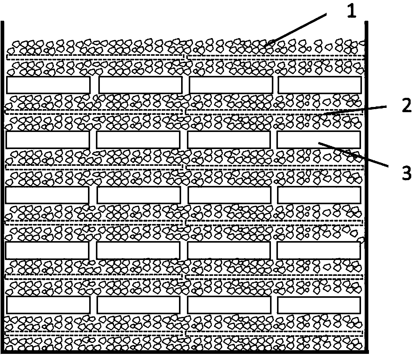
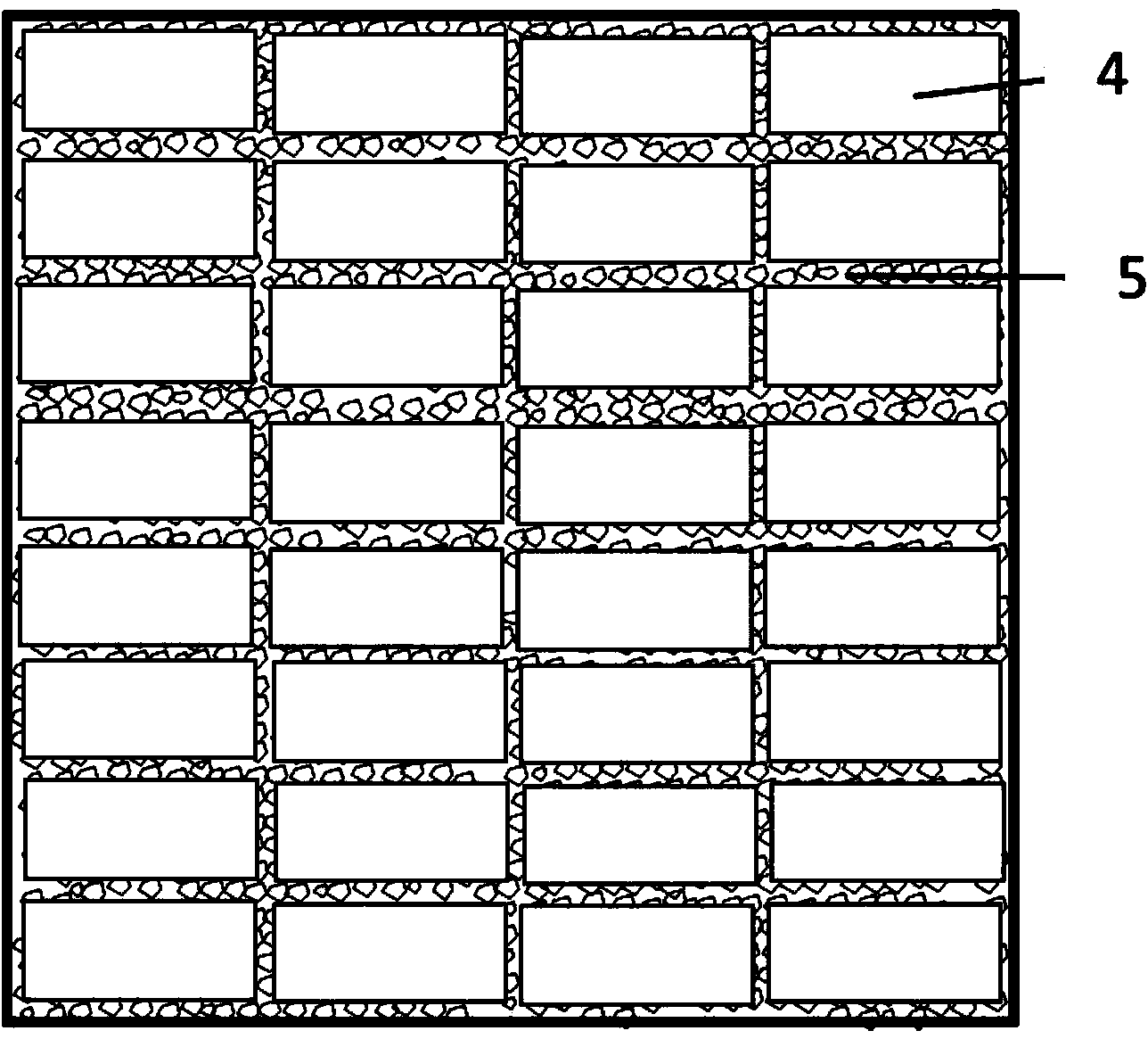
[0031] A vacuum melting furnace is used to smelt the configured raw materials under the protection of inert gas to form scales with a thickness of 0.1-0.5 mm. The metallographic grain boundaries of the R-Fe-B alloy scales are clear. The alloy scales are crushed mechanically, and jet milled after hydrogen explosion until the SMD is 3.4 μm. The magnetic field orientation press molding of 15KOe is used to make a compact, and the density of the compact is 3.95g / cm3. The compact is vacuum sintered in a sintering furnace, first sintered at 1080°C for 330 minutes, and then subjected to aging treatment (aging treatment means that the alloy workpiece is placed at a higher temperature or kept at room temperature after solid solution treatment, cold plastic deformation, or casting and forging. The heat treatment process whose performance, shape, and size change with time), aging at 480°C for 240 minutes to obtain a green body, the green body is multi-wire cut into a magnetic sheet of the...

Embodiment 2

[0040] The prepared raw materials are melted under the protection of an inert gas in a vacuum melting furnace to form scales with a thickness of 0.1-0.5 mm, and the obtained R-Fe-B alloy scales have clear metallographic grain boundaries. After the alloy flakes are HD and air-jet milled, the powder is SMD to 3.2 μm. After the air-jet milling powder is mixed, the magnetic field orientation of 15KOe is used to form a compact, and the compact density is 3.95g / cm3. The compact was vacuum sintered in a sintering furnace at 1090°C for 330min. Then perform aging treatment, aging at 480° C. for 240 minutes to obtain a green body. The green body is multi-wire cut into the magnetic sheet of the final product size, the size of the magnetic sheet: 40mm*30mm*2.4mm, the tolerance: ±0.03mm.

[0041] The surface of the magnetic sheet was washed with acid solution and deionized water, and dried to obtain the treated magnet M3. The composition of M3 is shown in Table 4. In order to prevent the...

Embodiment 3

[0050] The prepared raw materials are melted under the protection of an inert gas in a vacuum melting furnace to form scales with a thickness of 0.1-0.5 mm, and the obtained R-Fe-B alloy scales have clear metallographic grain boundaries. After the alloy flakes are HD and jet milled, the particle size of the jet milled powder obtained is SMD=3.2μm. After air-flow milling and mixing, the magnetic field orientation of 15KOe is used to form a compact, and the density of the compact is 3.95g / cm3. The compact was vacuum sintered in a sintering furnace at 1085°C for 300min. Then, aging treatment was performed, and the green body was obtained by aging at 490° C. for 240 minutes. The green body is multi-wire cut into magnetic sheets of the final product size. Magnet size: 50mm*15mm*6mm, tolerance: ±0.3mm.

[0051] The surface of the magnetic sheet was washed with acid solution and deionized water, and dried to obtain the treated magnet M5. The composition of M5 is shown in Table 6. ...


PUM

PropertyMeasurementUnit
particle diameteraaaaaaaaaa
thicknessaaaaaaaaaa
particle diameteraaaaaaaaaa

Abstract

The invention discloses a manufacturing method of an R-Fe-B sintered magnet. The manufacturing method of the R-Fe-B sintered magnet comprises the main steps of preparing a R1-Fe-B-M sintered magnet as a matrix; arranging an RLO particle layer of light rare earth element on the surface of the matrix and arranging a heavy rare earth RHX which comprises either dysprosium metal, or dysprosium hydride or both the dysprosium metal and the dysprosium hydride on the RLO particle layer; performing heating treatment inside a sintering furnace to enable the heavy rare earth RHX to evaporate to the surface of matrix by penetrating through the RLO particle layer and to diffuse from the surface to the inside of the magnet, wherein during the whole process, the RLO particle layer serves as transmission media and does not react with heavy rare earth elements. According to the manufacturing method of the R-Fe-B sintered magnet, the RLO particle layer of oxide and fluoride of light rare earth element is arranged between the magnet and the heavy rare earth RHX, so that on the one hand, non-direct contact of the magnet and the heavy rare earth RHX is achieved, on the other hand, the diffusion process of heavy rare earth RHX steam can be inhibited and slowed down, and excessive evaporation of the heavy rare earth RHX steam to the surface of the magnet can be prevented.

Description

technical field [0001] The invention relates to a method for manufacturing an R-Fe-B type sintered magnet, belonging to the field of rare earth permanent magnet materials. Background technique [0002] With the increasing demand for energy-saving motors in the automotive and electronic fields, the market application of R-Fe-B rare earth permanent magnets will be further expanded. Due to the need to use a large amount of heavy rare earth elements to increase the coercive force, the cost of the magnet will increase sharply. , so reducing the usage of heavy rare earth elements has become a research hotspot in the field of rare earth permanent magnets. Through the analysis of the microstructure of the magnet, it is confirmed that the way of diffusing heavy rare earth elements at the grain boundary can effectively reduce the scattering field at the grain boundary, weaken the magnetic exchange coupling effect, and harden the grain boundary magnetically, and the remanence of the ma...

Claims


Application Information

Patent Timeline
Patent Type & Authority Applications(China)
IPC IPC(8): H01F41/02H01F1/057H01F1/08B22F3/16
CPCH01F1/0536
Inventor 于永江李咚咚李志强侯晓红杜伟
Owner YANTAI ZHENGHAI MAGNETIC MATERIAL CO LTD
Why Eureka
Try Eureka