System for measuring and indicating changes in the resistance of a living body

a technology of resistance and living body, which is applied in the field of improved devices for indicating and measuring variations in resistance of living bodies, can solve the problems of inability to accurately indicate the measured changes, masking or falsely reporting small measurements, etc., and achieves the effect of eliminating undesirable characteristics in the measurement signal and maintaining the sensitivity of the device at a constant level

Inactive Publication Date: 2000-01-04
CHURCH OF SPIRITUAL TECH
View PDF4 Cites 68 Cited by
  • Summary
  • Abstract
  • Description
  • Claims
  • Application Information

AI Technical Summary

Benefits of technology

It is an advantage of the present invention that the sensitivity of the device is maintained at a constant level.
In accordance with the objects, features and advantages of the present invention, an improved electrical resistance measuring or indicating device comprising a resistance measuring circuit having input leads connected to a living body for producing measurement signals representative of the resistance of a living body is provided. An amplifier circuit receives the measurement signals and amplifies them to a perceptible level. An indicator circuit receives the amplified signals and provides the measurement signals in a perceptible form. The present invention advantageously includes passive and active devices to eliminate undesirable characteristics in the measurement signal.
One feature of the present invention is an ac

Problems solved by technology

Although adequately suited for its intended purpose of detecting changes in the resistance of a living body, it was not able to accurately indicate the measured changes.
One problem with these devices is that undesi

Method used


Image

  • System for measuring and indicating changes in the resistance of a living body
  • System for measuring and indicating changes in the resistance of a living body
  • System for measuring and indicating changes in the resistance of a living body

Examples


Embodiment Construction

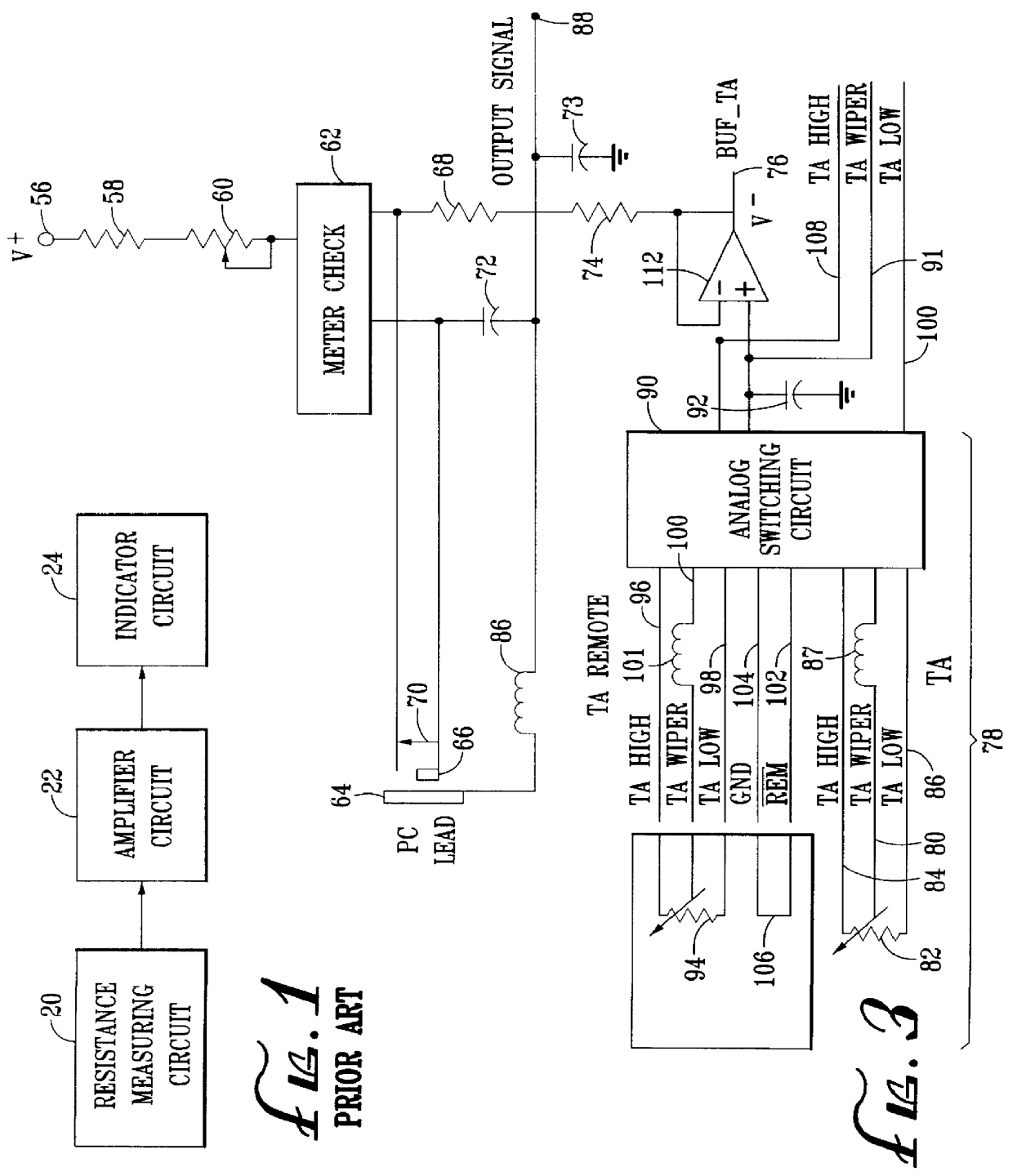
Referring to the figures for purposes of illustration, the present invention may be used in combination with any conventional three stage circuits for measuring and indicating changes in the resistance of a living body. With reference to FIG. 1, such devices typically use a resistance measuring circuit 20 to transform measured resistances across a living body in the form of a measurement signal. The resistance measuring circuit connects to the amplifier circuit 22 that amplifies the measured signal to a perceptible level. An indicator circuit 24 connected to the amplifier circuit 22 produces the measured signal in a perceptible form. The resistance measuring circuit 20 may accomplish such measurements using a bridge or voltage divider circuit of the type conventional for measuring the resistance of a living body. A three stage circuit incorporating a bridge circuit of the type suitable for this purpose is disclosed in U.S. Pat. No. 4,702,259, U.S. Pat. No. 4,459,995 and U.S. Pat. No...


PUM


Abstract

A system for measuring changes in the resistance of a living body includes a resistance measuring circuit, an amplifier circuit and an indicator circuit in which the amplifier circuit includes a calibration circuit to give a generally constant amplitude response to a given measured input. Radio frequency insulators are included to reduce noise in the system. The circuits are operated such that when an overall change in the resistance of a living body occurs, the resistance measuring circuit is adjusted to determine the overall resistance. To account for changes in sensitivity caused by the overall change in resistance, the gain of the amplifier circuit is automatically adjusted to thereby maintain a generally constant amplitude response.

Description

1. Field of the InventionThis invention relates to an improved device for indicating and measuring variations in the resistance of a living body.2. Prior ArtWith the advent of Lafayette R. Hubbard's device for measuring and indicating changes in a living body, the capability of discerning small changes in the resistance of living body through electromechanical measurement was made available. That device includes, generally, a resistance measuring circuit, an amplifier circuit and an indicator circuit. Although adequately suited for its intended purpose of detecting changes in the resistance of a living body, it was not able to accurately indicate the measured changes. Various improvements have attempted to overcome this problem, described and illustrated in U.S. Pat. No. 3,290,589 and U.S. Pat. No. 4,459,995. Such devices operate to generate a signal representative of small measurements in the resistance of a living body. This is then amplified into a signal that is discernable and ...

Claims


Application Information

Patent Timeline
IPC IPC(8): A61B5/05A61B5/053G11B23/03G11B23/04H01Q1/12H01Q1/32H01Q23/00H04B1/08H04B1/20H04H1/00
CPCA61B5/05G11B23/0327G11B23/049H01Q1/3291H01Q23/00H04B1/08H01Q1/1271H04B1/20
Inventor HUBBARD, DECEASED, LAFAYETTE RONSTARKEY, LEGAL REPRESENTATIVE, BY NORMAN F.MCCORMICK, JOHNSTAVROPOULOS, JAMESSTINNETT, RICHARD
Owner CHURCH OF SPIRITUAL TECH
Why Eureka
Try Eureka