Method for growing thin films

Inactive Publication Date: 2000-01-18
ASM AMERICA INC
View PDF26 Cites 623 Cited by
  • Summary
  • Abstract
  • Description
  • Claims
  • Application Information

AI Technical Summary

Problems solved by technology

If the starting materials are allowed to mix with each other prior to reaching the substrate surface as is the case in the CVD method, for instance, a chance of their premature mutual reaction arises.
Then, the risk of microparticle formation already within the inflow channels of the gaseous reactants is imminent.
Such microparticles have a deteriorating effect on the quality of the thin film growth.
However, notwithstanding the high reliability of the above-described arrangement, it has some disadvantages.
For instance, the cross sections and shapes of piping in practical reactor constructions vary between, e.g., the infeed manifold and the substrates, whereby the thickness and shape of the diffusion wall become difficult to control and the starting materials may become carried over into contact with each other.
The diffusion wall may also become destroyed in the nozzles feeding the vapor-phase reactant to the substrates, in gas mixers or at other discontinuity points of the piping.
The laminarity of gas inflow may also become disturbed by a too tight bend in the piping.
Intermixing of starting materials in flow systems cannot be prevented simply by keeping the gas volumes apart from each o

Method used


Image

  • Method for growing thin films
  • Method for growing thin films

Examples


Example

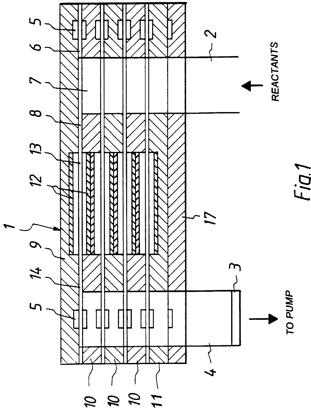
The following example describes the design principles for the pump of the apparatus shown in FIG. 1 and the interval between the successive vapor-phase reactant pulses, respectively, that make the apparatus perform in accordance with the invention:

The pump capacity is selected as 360 m.sup.3 / h, or 360.times.1000 / 3600 (l / s)=100 l / s Hence, the above-calculated total gas volume can be evacuated with a pump so dimensioned in approx. 0.2 s.

A pump with the above-calculated capacity requires a pumping line with an inner diameter of 76 mm, having a volume per length unit of .pi..times.0.38.times.0.38.times.10 dm.sup.3 =4.07 l / min, which means that if the length of the pumping line from the reaction chamber pack to the outlet connection of the apparatus is 1 m, for instance, its evacuation takes an extra time of 0.04 s.

Accordingly, the interval between the reactant pulses in the above example is selected as approx. 0.25 s, which is a sufficient time for one-time evacuation of the entire gas...


PUM

PropertyMeasurementUnit
Fractionaaaaaaaaaa
Flow rateaaaaaaaaaa
Volumeaaaaaaaaaa

Abstract

PCT No. PCT/FI95/00658 Sec. 371 Date Sep. 25, 1996 Sec. 102(e) Date Sep. 25, 1996 PCT Filed Nov. 28, 1995 PCT Pub. No. WO96/17107 PCT Pub. Date Jun. 6, 1996A method for growing a thin film on a substrate. A substrate is placed in a reaction space. The substrate is subjected to at least two vapor phase reactants in the form of vapor phase pulses, repeatedly and alternately. Gas within the reaction space is purged between two successive vapor phase pulses essentially entirely by use of a pump connected to the reaction space. The reaction space is purged between two successive vapor phase pulses such that less than 1% of the residual components from the first vapor phase pulse remains prior to the inflow of the second vapor phase pulse.

Description

1. Field of the InventionThe present invention relates to a method for growing thin films on substrates placed in a reaction space and subjected to alternately repeated surface reactions of a least two vapor phase reactants.In the present method, the substrate is typically located in a reaction space, wherein it in accordance with the Atomic Layer Epitaxy (ALE) method is subjected to alternately repeated surface reactions of at least two different reactants. According to the present method, the reactants are admitted repetitively and alternately each reactant at a time from its own source in the form of vapor-phase pulses into the reaction space. Here, the vapor-phase reactants are allowed to react with the substrate surface for the purpose of forming a solid-state thin film on the substrate.While the method is most appropriately suited for producing so-called compound thin films using as the reactants such starting materials that contain component elements of the desired compound t...

Claims


Application Information

Patent Timeline
IPC IPC(8): C23C16/455C30B25/10C30B25/14C23C16/44C30B25/02C23C16/52C30B29/46C30B35/00
CPCC23C16/455C23C16/45525C23C16/45527C23C16/45546C30B25/10C30B25/14C23C16/44
Inventor SUNTOLA, TUOMOLINDFORS, SVEN
Owner ASM AMERICA INC
Why Eureka
Try Eureka