Method of detecting the angle of rotation and load torque of a DC motor, and apparatus of detecting the angle of rotation and load torque of a DC motor

a dc motor and angle detection technology, applied in the direction of field or armature current control, non-deflectable wheel steering, underwater vessels, etc., can solve the problems of difficult to estimate the load torque, the operation of the steering system cannot be controlled, and the motor can not operate normally

Inactive Publication Date: 2000-01-18
MITSUBISHI ELECTRIC CORP
View PDF15 Cites 39 Cited by
  • Summary
  • Abstract
  • Description
  • Claims
  • Application Information

AI Technical Summary

Problems solved by technology

In general, locking can occur in the operation of a motor when a trouble occurs in a motor itself or in a transmission mechanism such as a gear for transmitting power from a motor to a load.
If such locking occurs in a motor used in a steering system of a car, a steering wheel will be locked, and it will become impossible to control the operation of the steering system.
If the system has no angular velocity detector such as a tachometer generator or a motor angle detector such as a potentiometer, it is difficult to estimate the load torque or the system will be very expensive even if possible.
In general, however, when the motor is

Method used


Image

  • Method of detecting the angle of rotation and load torque of a DC motor, and apparatus of detecting the angle of rotation and load torque of a DC motor
  • Method of detecting the angle of rotation and load torque of a DC motor, and apparatus of detecting the angle of rotation and load torque of a DC motor
  • Method of detecting the angle of rotation and load torque of a DC motor, and apparatus of detecting the angle of rotation and load torque of a DC motor

Examples


embodiment 2

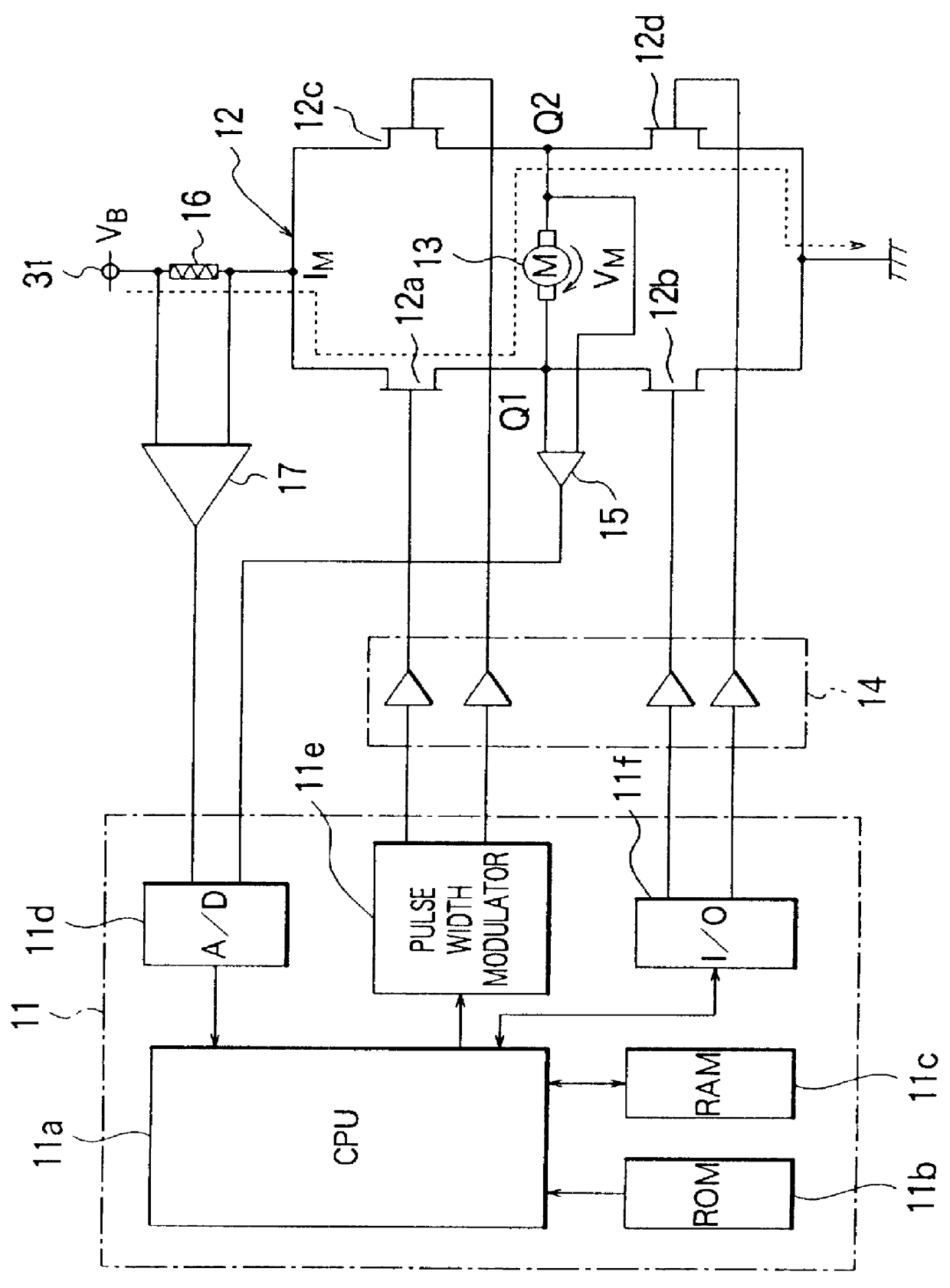
FIG. 4 illustrates a DC motor controller according to a second embodiment of the present invention. In FIG. 4, equivalent or similar parts to those in FIG. 1 are denoted by similar reference numerals, and will not be described here in further detail. In the specific embodiment described above with reference to FIG. 1, the motor current I.sub.M is controlled substantially by means of software. Instead, in this second embodiment, there is provided a motor current control means 18 whereby the motor current I.sub.M is controlled by means of hardware. Therefore, the microcomputer 11a used in this embodiment no longer has a pulse width modulator 11e such as that employed in the microcomputer 11 of the first embodiment. Instead, the pulse width modulator is incorporated in the motor current control means 13. The other parts are similar to those shown in FIG. 1.

FIG. 5 illustrates a specific circuit implementing the motor current control means 18.

As shown in FIG. 5, the motor current control...

embodiment 3

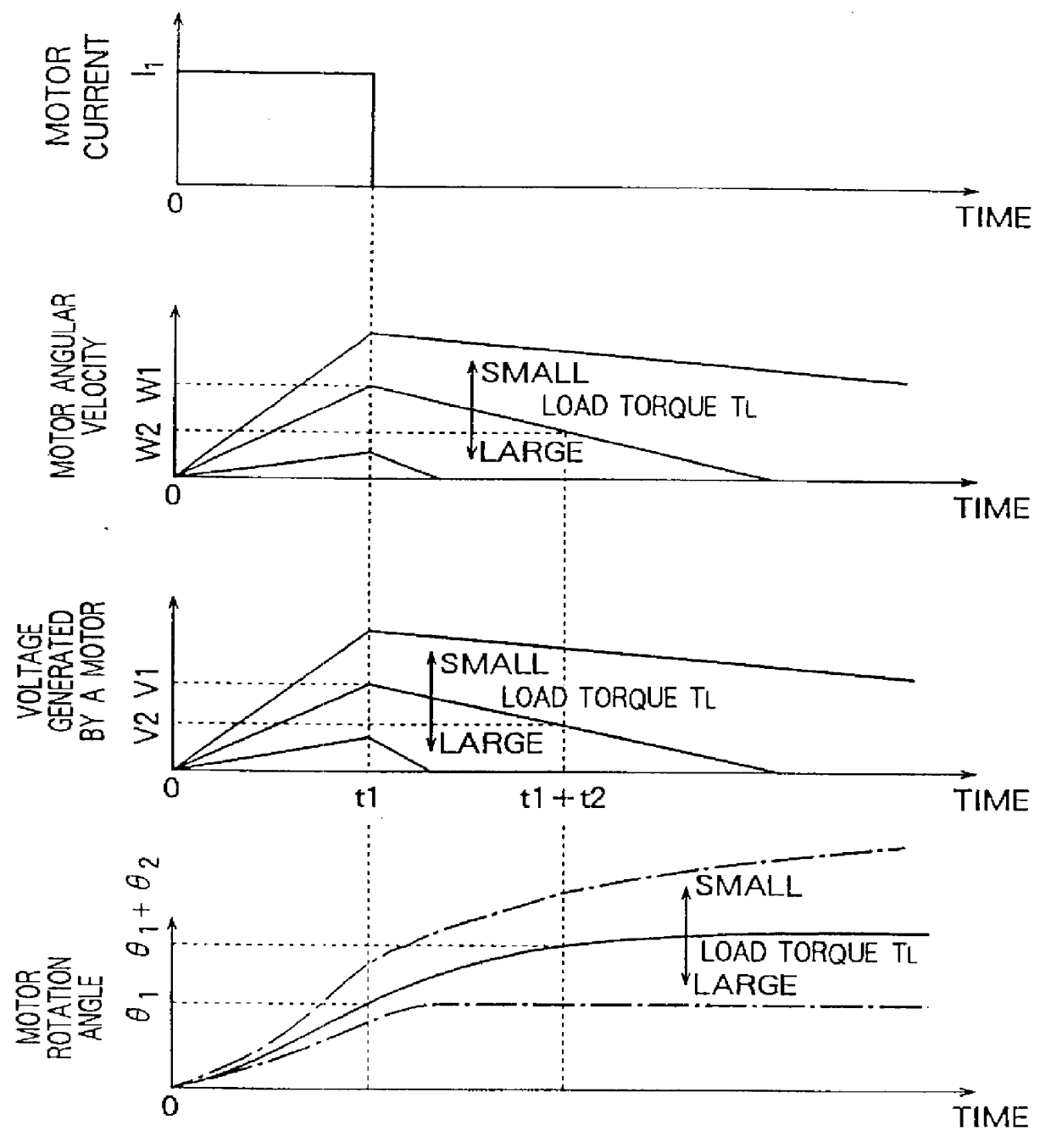
In the first embodiment described above, the driving current I.sub.1 and driving time period t.sub.1 can be set to arbitrary values without particular limitations. However, if these values are set so that an rotation angle .theta. equal to or greater than for example 360.degree. is obtained in the rotation of the DC motor 13 or in the rotation of a reduction gear connected to the DC motor 13 even when the load torque T.sub.L becomes smaller than a predetermined value, then it becomes possible to more surely detect an increase in the load torque T.sub.L due to for example incorporation of a foreign substance into the gear or motor system.

In this embodiment, as described above, when the load torque T.sub.L is smaller than the predetermined value, the rotation angle of the DC motor 13 or the rotation angle of the reduction gear connected to the DC motor 13 becomes greater than the predetermined value. This makes it possible to more surely detect an increase in the load torque due to fo...

embodiment 4

In the previous embodiments, the driving current I.sub.1 is set to a constant value. Instead, the driving current I.sub.1 may be varied with time. For example, the driving current I.sub.1 may be varied in accordance with a ramp function as shown in FIG. 6. In this case, equations (5) and (11) are modified into equations (12) and (13), respectively, as represented below:

.theta..sub.1 =t.sub.1.sup.2 (k.sub.T .multidot.I.sub.2 -T.sub.L) / 2J=.omega..sub.1 t.sub.1 / 2 (12)

T.sub.L =k.sub.T -I.sub.2 -2J.theta..sub.1 .multidot.1 / t.sub.1.sup.2(13)

where I.sub.2 is a current value when a last driving is performed.

In the case where the driving current I.sub.1 is set to a constant value, the target value of the motor current I.sub.M changes in a step fashion, and thus overshooting can occur in the current depending on the setting of the driving current and the driving time, and also on the design of the current control system (feedback control system). The overshoot can produce an error in the det...


PUM


Abstract

A method of detecting the angle of rotation of a DC motor includes the steps of: driving the DC motor with a predetermined torque for a predetermined period of time which is selected so that the angular acceleration of the DC motor is substantially constant during the above period of time; and calculating the angle of rotation of the DC motor from the driving time period and the voltage generated by the DC motor after the driving of the DC motor is stopped. This method makes it possible to accurately detect the angle of rotation and the load torque using an apparatus having a simple structure.

Description

1. Field of the InventionThe present invention relates to a method of detecting the angle of rotation of a DC motor, a method of detecting the load torque, and an apparatus of detecting the angle of rotation of a DC motor, an apparatus of detecting the load torque.2. Description of the Related ArtIn general, locking can occur in the operation of a motor when a trouble occurs in a motor itself or in a transmission mechanism such as a gear for transmitting power from a motor to a load. If such locking occurs in a motor used in a steering system of a car, a steering wheel will be locked, and it will become impossible to control the operation of the steering system.One known technique to solve the above problem is to mechanically isolate the output shaft of the motor from the steering system by controlling the clutch when an abnormality is detected in the load torque of the motor estimated from the driving current and the angle of rotation or the angular acceleration velocity of the mot...

Claims


Application Information

Patent Timeline
IPC IPC(8): B62D5/04H02P7/00H02P7/06H02P29/00
CPCB62D5/0478B62D5/0487H02P7/0044H02P7/04
Inventor MIURA, KAZUNORITAKAGI, MASANORIKIFUKU, TAKAYUKIOHTAGAKI, SHIGEKI
Owner MITSUBISHI ELECTRIC CORP
Why Eureka
Try Eureka