Oscillation damper for damping fluid oscillation in a hydraulic anti-slip control braking system in motor vehicles

a technology of oscillation damper and hydraulic braking system, which is applied in the direction of brake cylinder, servomotor, braking system, etc., can solve the problems of structural difficulties in disposing the known type of vibration damper, which requires a relatively large installation diameter, etc., and achieves adequate damping effect, low rigidity, and sufficient compression volume

Inactive Publication Date: 2000-01-25
ROBERT BOSCH GMBH
View PDF2 Cites 26 Cited by
  • Summary
  • Abstract
  • Description
  • Claims
  • Application Information

AI Technical Summary

Benefits of technology

The vibration damper of the invention has the advantage over the prior art that the volume required for the vibration damping extends over a chamber of small diameter and of corresponding axial length. This kind of shaping can typically be achieved without difficulties in a housing. Another advantage is that the requisite damping volume is furnished on both sides of the jacket wall of the shaped part forming the diaphragm. The support body advantageously assures that the shaped part will not collapse when pressure is imposed, yet nevertheless, with the aid of the groove in the side face, a sufficient compression volume with low rigidity is available. Finally, the fitting of the shaped part over the support body is advantageous upon assembly and in sealing in the bore of the housing.
By the provision disclosed herein, in cooperation with a flat extension end face and a dimensionally rigid bottom wall of the shaped part, an open communication is always achieved between the interior of the shaped part and the chamber of the extension.
With the refinement of the invention defined by hereinafter, it is advantageously attained that the jacket wall of the shaped part, on pressing against the side faces of the support body, conforms to the inside of the grooves, beginning at the foot of the support body. This prevents the inclusion of air bubbles between the jacket wall and the support body.
With the shaping of the bottom wall of the shaped part, the bore leading to the chamber in the support body is kept open in a simple way.
An advantage of the invention is that, a diversion of the hydraulic forces acting upon the support body to the housing is attained over a short distance.
To achieve an adequate damping effect in the intake-side pressure region, the chamber in the extension of the support body communicates with the ambient air. The embodiment of the invention including a covering cap assures the attainment of an air exchange protected against becoming soiled.

Problems solved by technology

Since in modern brake systems the elements located between the master cylinder and the wheel brake cylinders, such valves, pumps, lines and the like, have undergone miniaturization of their structural volume and a tightly packed arrangement in a so-called hydraulic unit, primarily for the sake of saving weight and expense, difficulties arise structurally in disposing the known type of vibration damper, which requires a relatively large installation diameter, in the housing of the hydraulic unit.

Method used


Image

  • Oscillation damper for damping fluid oscillation in a hydraulic anti-slip control braking system in motor vehicles
  • Oscillation damper for damping fluid oscillation in a hydraulic anti-slip control braking system in motor vehicles
  • Oscillation damper for damping fluid oscillation in a hydraulic anti-slip control braking system in motor vehicles

Examples


Embodiment Construction

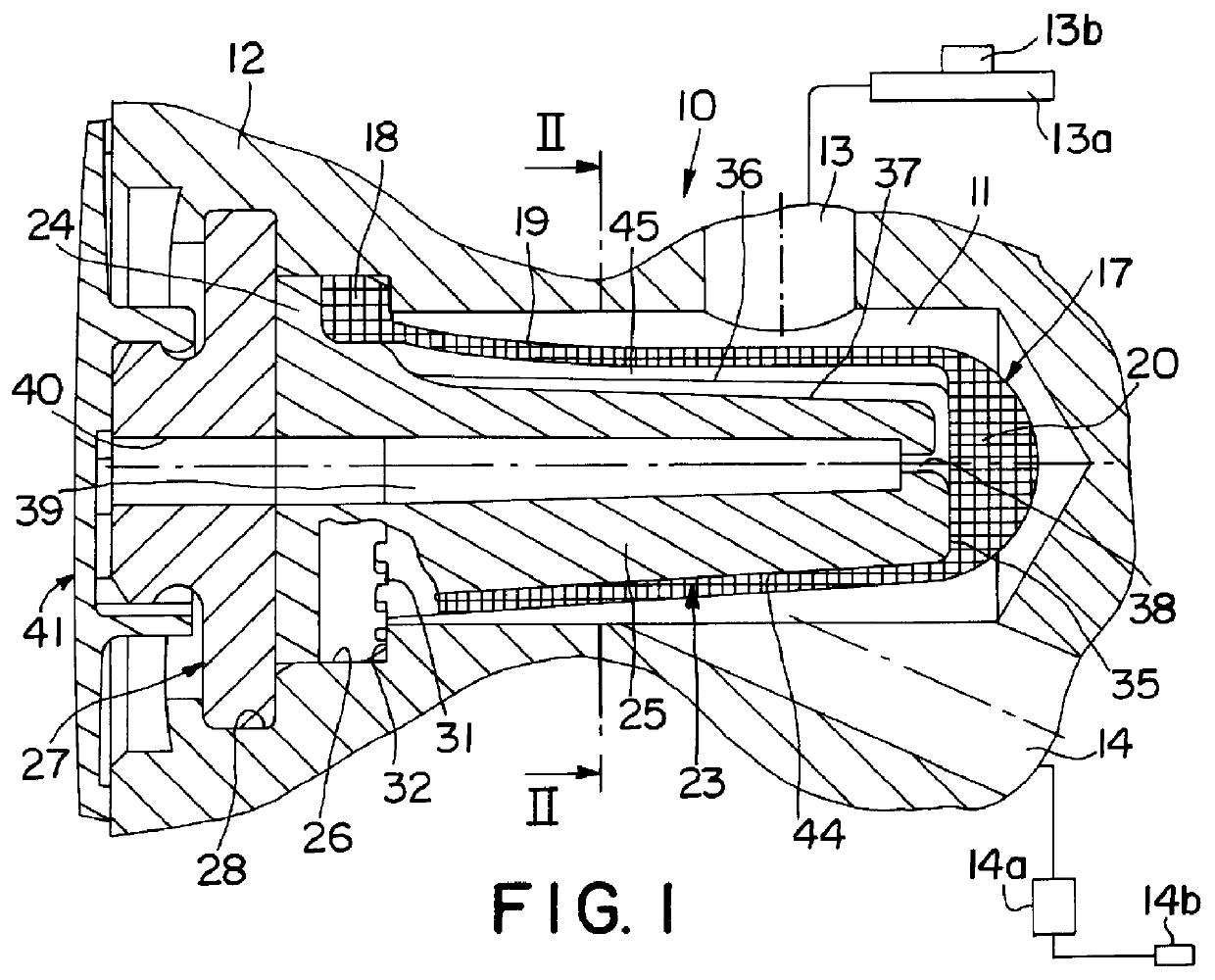
A vibration damper 10, shown in FIG. 1 of the drawing, for damping fluid vibrations is intended for use in a hydraulic slip-controlled brake system of motor vehicles, of the kind described in the reference DE 43 36 464 A1 referred to at the outset. The vibration damper 10 is disposed in a bore 11 of a housing 12, which also receives valves, pumps, lines and other elements of the aforementioned brake system. The bore 11 of the housing 12 has a depth that is a multiple of its diameter. It communicates, through a line segment 13, with a master cylinder 13a having a storage container 13b for brake fluid, and through a line segment 14, it communicates both with the suction side of a self-aspirating reciprocating piston pump 14a and with at least one wheel brake cylinder 14b. With the pump, brake pressure can be generated in the wheel brake cylinder in the drive slip control mode.

The vibration damper 10 has a shaped part 17, acting as a diaphragm, which is made of the brake fluid-resistan...


PUM


Abstract

PCT No. PCT/DE96/00917 Sec. 371 Date Feb. 23, 1998 Sec. 102(e) Date Feb. 23, 1998 PCT Filed May 25, 1996 PCT Pub. No. WO97/02971 PCT Pub. Date Jan. 30, 1997The vibration damper has a sleevelike shaped part comprising an elastomer as a diaphragm. The shaped part is received tightly on the opening end of a bore of a housing and surrounds an extension of a support body disposed in the bore. Provided on a side face of the extension is a groove, which communicates with a chamber in the extension. The shaped part, which on its outside is exposed to the brake fluid, with the inside of its jacket wall defines a hollow chamber, formed toward the extension of the support body and having atmospheric pressure. The vibration damper can be used in a slip-controlled hydraulic brake systems of motor vehicles.

Description

PRIOR ARTThe invention is based on a vibration damper for damping fluid vibrations in a hydraulic, slip-controlled brake system for a motor vehicle.One such vibration damper is already known (German Patent Disclosure DE 43 36 464 A1), having a circular, substantially flat diaphragm. A closure cap that retains the diaphragm in the housing bore acts as a fixed boundary wall for the hollow chamber, which through a bore in the cap communicates with the ambient air.The vibration damper serves, in the drive slip control mode, to avert longitudinal vibration, caused by the pump type used in the brake system, of the brake fluid in the pump intake line, as well as to avoid vibration cavitation, so that the pump can supply an adequately large volumetric flow for a rapid pressure buildup in the wheel brake cylinders. Another goal of the vibration damper is to reduce the pressure surge that occurs in the line to the master cylinder when the drive slip control mode ends.To achieve an adequate da...

Claims


Application Information

Patent Timeline
Patent Type & Authority Patents(United States)
IPC IPC(8): B60T8/40B60T8/48B60T8/36F15B1/08F15B11/00F16L55/04F16L55/05
CPCB60T8/368B60T8/4068B60T8/4872B60T8/48
Inventor SCHNEIDER, STEFFENALAZE, NORBERTHOFMANN, DIRKPECHTOLD, ULRICHSTRATMANN, EGONHAECKER, JUERGENSCHWARZ, HANS-FRIEDRICHMITTWOLLEN, NORBERT
Owner ROBERT BOSCH GMBH
Why Eureka
Try Eureka