Spider fitting for multi-module filter system, and motive cart assembly comprising same

a filter system and multi-module technology, applied in the direction of filtration separation, membranes, separation processes, etc., can solve the problem of requiring substantial volume of work spa

Inactive Publication Date: 2000-01-25
SMARTFLOW TECH
View PDF6 Cites 113 Cited by
  • Summary
  • Abstract
  • Description
  • Claims
  • Application Information

AI Technical Summary

Benefits of technology

It is another object of the present invention to provide a multi-module filter system of such type, which is spatially and volumetrically compact.
It is a further object of the invention to provide a multi-module filter system of the foregoing type, which is readily mobile in character, being easily transportable within a processing facility from one location to another, as for example from an active processing location to a cleaning or maintenance location.
In one aspect, the present invention relates to a multi-arm spider fitting which is usefully employed to interconnect corresponding ends of a number of filter modules, in a highly compact and hydrodynamically efficient manner.
By the multi-module filter assembly of the invention, a multiplicity of filter modules can be accommodated within a significantly smaller volume than the multi-module filter systems of the prior art. As a result of such compactness, the multi-module filter systems of the invention may be mounted on a cart or other motive structure, for ready transport from one location to another in the process facility in which the filter modules are employed. By such mobility, the filter modules can be quickly and conveniently transported from an active processing site in the process facility to a sterilization or maintenance site at another location of the facility, thereby simplifying the overall layout and design of the process facility, and permitting the ancillary equipment associated with the filter modules to be likewise conveniently and compactly situated.

Problems solved by technology

Such multi-module filter systems of the prior art, despite their "flat" conformation, nonetheless require substantial volume of work space in the pharmaceutical or other process facility, and constitute stationary or permanent installations which are not susceptible of transport except with difficulty.

Method used


Image

  • Spider fitting for multi-module filter system, and motive cart assembly comprising same
  • Spider fitting for multi-module filter system, and motive cart assembly comprising same
  • Spider fitting for multi-module filter system, and motive cart assembly comprising same

Examples


Embodiment Construction

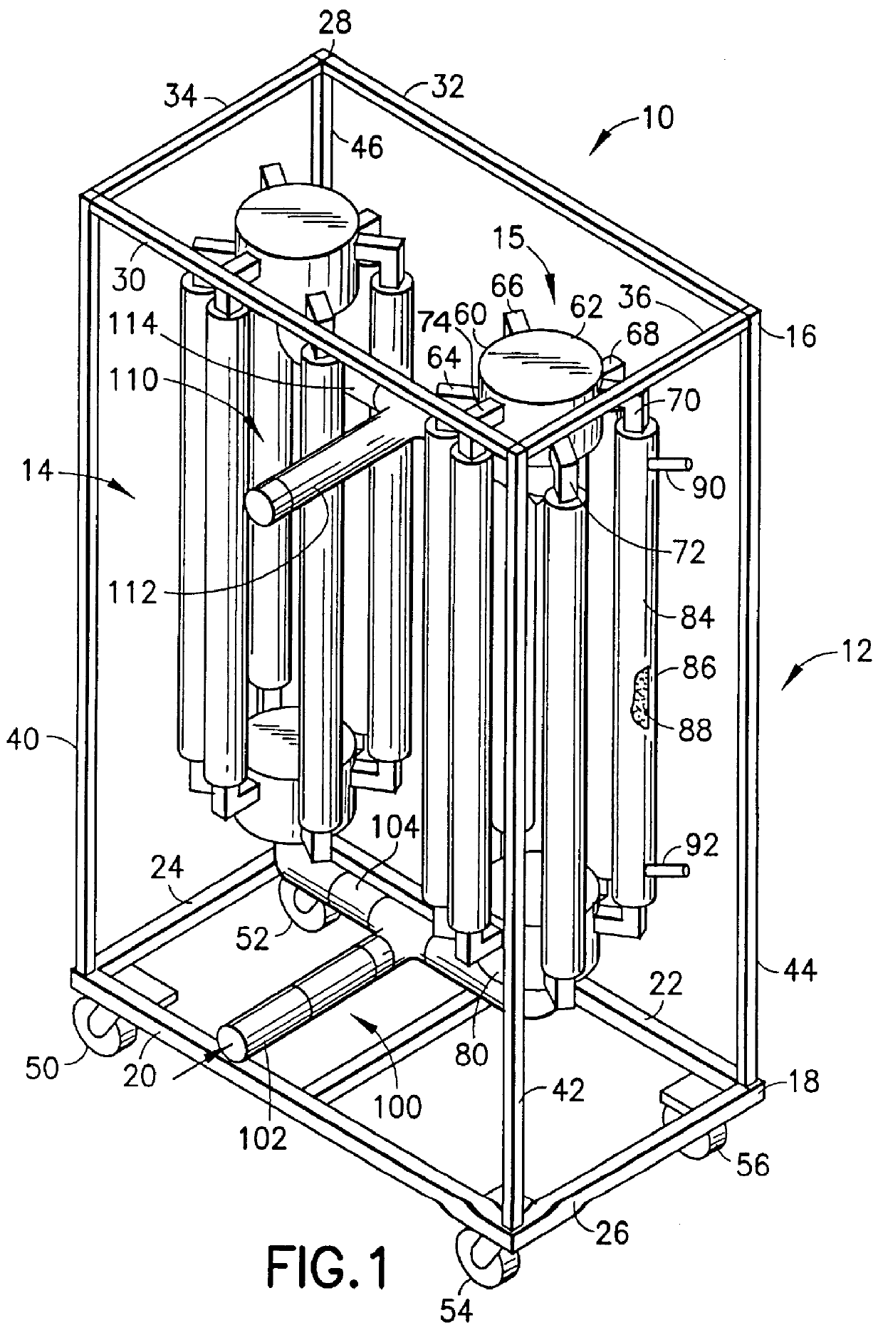
Referring now to the drawings, FIG. 1 is a perspective view of a motive cart assembly 10, including a cart 12 and side-by-side arrays of multi-module filter assemblies 14 and 15, manifolded as hereafter described.

The cart 12 in the embodiment shown comprises a rectangular frame 16 including a rectangular base 18 formed by front beam 20, back beam 22 and side beams 24 and 26 joined at their extremities as shown to define the rectangular base portion. Correspondingly, the cart 12 comprises a top portion 28 formed by front beam 30, rear beam 32 and side beams 34 and 36, constructed similarly to the base portion. The base portion and top portion of the cart are interconnected by vertical upstanding beams 40, 42, 44 and 46, as illustrated.

The base portion 18 of the cart has rollers 50, 52, 54 and 56 mounted on the underside thereof, to provide motive transport capability to the cart. The rollers 50, 52, 54 and 56 may be of a swivel or caster type, to provide increased motive flexibility ...


PUM

PropertyMeasurementUnit
circumferenceaaaaaaaaaa
volumeaaaaaaaaaa
volumeaaaaaaaaaa

Abstract

A multi-arm spider fitting including a central hub from which such arms radiate. The arms are adapted at their extremities for coupling with filter modules, so that multiple filter modules can be secured to a single spider fitting, with the filter modules being arranged in a compact array to minimize the volumetric and spatial requirements of the filtration system. The multi-module filter assembly may be mounted on a motive cart, to provide for ready transport of the filter assembly between locations in a process plant.

Description

1. Field of the InventionThis invention relates to a spider fitting for a multi-module filtration system, utilizing for example elongate microfiltration or ultrafiltration modules in which a feed material is subjected to filtration to yield filtrate (permeate) and retenate streams. The invention also relates to a motive cart assembly comprising a multi-module filtration system utilizing such spider fittings, for enhanced ease and flexibility of filtration processing and filter system sterilization for use.2. Background of the InventionA wide variety of filtration systems are in use for pharmaceutical processing and a wide variety of other industrial manufacturing operations.The filtration systems conventionally used in pharmaceutical, biological and bioprocessing applications involve membranes which are manufactured to yield highly discriminatory filtration of feed streams involving critical concentration and fractionation characteristics in the respective permeate and / or retenate s...

Claims


Application Information

Patent Timeline
Patent Type & Authority Patents(United States)
IPC IPC(8): B01D61/14B01D61/20B01D63/04B01D61/18B01D65/00B01D29/11
CPCB01D29/118B01D61/142B01D61/18B01D61/20B01D63/046B01D65/00B01D29/52B01D29/90B01D29/945B01D2201/0469B01D2313/105B01D2313/125B01D61/146
Inventor KOPF, HENRY B.
Owner SMARTFLOW TECH
Why Eureka
Try Eureka