Rugate induced transmission filter

a transmission filter and induced technology, applied in the field of optical filters, can solve the problems of difficult to address applications requiring extended passbands at wavelengths shorter than the reflection bands, unsatisfactory family of rejection lines at progressively shorter wavelengths, and easy mechanical failure of interfaces between multiple layers

Inactive Publication Date: 2000-02-01
THE BF GOODRICH CO
View PDF2 Cites 35 Cited by
  • Summary
  • Abstract
  • Description
  • Claims
  • Application Information

AI Technical Summary

Problems solved by technology

An interference resonance is also produced for input light having wavelengths .lambda..sub.i, where .lambda..sub.i =.lambda..sub.o / m for odd values of m. These harmonics result in an undesirable family of rejection lines at progressively shorter wavelengths.
In addition, interfaces between the multiple layers are prone to mechanical failure when exposed to high temperatures or mechanical stresses.
However, due to the creation of undesirable reflection lines at .lambda..sub.o / m wavelengths, applications requiring extended passbands at wavelengths shorter than the reflection bands are difficult to address.
Also, accurate positioning of the multiple passbands is exceedingly difficult due to manufacturing limitations.
In addition, as the number and width of the rejection bands increase, so does the thickness and unreliability of the filters.
This increases the price and decreases the design flexibility of the filters.
Still, when exposed to high power lasers, such filters tend to de-laminate at the interfaces between the layers due to differences in thermal expansion coefficients of the layer materials.
However, these filters only operate at a single bandpass wavelength and have relatively poor transmission efficiency.
This can be an expensive and painstaking process.
Also, as the passband narrows, successful placement and shaping of the passband becomes increasingly difficult.
This approach however, requires accurate placement of the phase discontinuity which may be difficult in some applications.

Method used


Image

  • Rugate induced transmission filter
  • Rugate induced transmission filter
  • Rugate induced transmission filter

Examples


Embodiment Construction

While the present invention is described herein with reference to illustrative embodiments for particular applications, it should be understood that the invention is not limited thereto. Those having ordinary skill in the art and access to the teachings provided herein will recognize additional modifications, applications, and embodiments within the scope thereof and additional fields in which the present invention would be of significant utility.

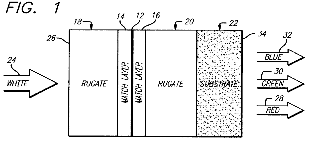
FIG. 1 is a diagram of a tristimulus rugate transmission filter 10 constructed in accordance with the teachings of the present invention. The filter 10 includes a metallic absorption layer 12 sandwiched between a first matched layer 14 and a second matched layer 16. A first rugate layer 18 is deposited on the first matched layer 14 and a second rugate layer 20 is deposited on the second matched layer 16. The layers 12, 14, 16, 18, 20 are supported by a transparent substrate 22 adjacent to the second rugate layer 20. The layers 12, 14, 16, 1...


PUM

PropertyMeasurementUnit
thickaaaaaaaaaa
thicknessaaaaaaaaaa
thickaaaaaaaaaa

Abstract

A filter (10) for selectively transmitting electromagnetic energy over a range of frequencies (28, 30, 32) adapted for use with white light (24). The filter (10) includes rugate layers (18, 20) for creating a resonant cavity that resonates at desired bandpass frequencies (28, 30, 32). An absorptive layer (12) absorbs frequencies near the bandpass frequencies (28, 30, 32) and reflects frequencies outside the bandpass frequencies (28, 30, 32). Phase matching layers (14, 16) allow the transmission of electromagnetic energy within the transmission bands (28, 30, 32) through the absorption layer 12. In an illustrative embodiment, the bandpass frequencies (28, 30, 32) comprise the three tristimulus frequencies, i.e., red (28), green (30) and blue (32) frequencies. The rugate layers (18, 20) include first (18) and second (20) rugate layers made of SiO2 and Ta2O5, respectively. Located between the first (18) and second (20) rugate layers is the absorption layer (12) that is surrounded by the first (14) and second (16) phase matching layers. The absorption layer (12) is a silver layer that is approximately 500 angstroms thick. The first rugate layer (18) has a first index of refraction versus layer thickness profile representing a superposition of sinusoids. Each sinusoid has a frequency directly corresponding to tristimulus band frequency. The second rugate layer (20) has a second index of refraction versus layer thickness profile that is a phase-adjusted version of the first index of refraction versus layer thickness profile. Both rugate layers (18, 20) have index or refraction versus layer thickness profiles have several cycles.

Description

1. Field of InventionThis invention relates to optical filters. Specifically, the present invention relates to devices for transmitting light of certain wavelengths and blocking light of other wavelengths.2. Description of the Related ArtMultispectral bandpass optical filters are used in a variety of demanding applications ranging from laser protection glasses to virtual reality imaging applications. Such applications require reliable, durable filters that accurately transmit light of specific wavelengths.A conventional discrete layer rejection filter includes a stack of optical films, i.e., layers. The indices of refraction of the layers alternate between high and low levels. The alternating indices have a resonating effect on an input light beam resulting in one or more reflection bands, i.e., rejection lines. (A rejection line or reflection band is a portion of the spectrum of the input light that is reflected and not transmitted.)The stack of layers is called a quarter-wave stac...

Claims


Application Information

Patent Timeline
Patent Type & Authority Patents(United States)
IPC IPC(8): G02B5/28
CPCG02B5/289
Inventor TURNER, AARON N.
Owner THE BF GOODRICH CO
Why Eureka
Try Eureka