Apparatus for detecting foreign matter with high selectivity and high sensitivity by image processing

a technology of image processing and foreign matter, applied in the field of apparatus for detecting foreign matter with high selectivity and high sensitivity by image processing, can solve the problems of low contaminant detection sensitivity and difficulty in discriminating between contaminant signal and false-reject signal from each other, and achieve high selectivity, high sensitivity, and effectively suppressing false-reject signal

Inactive Publication Date: 2000-02-08
ANRITSU SANKI SYSTEM CO LTD
View PDF8 Cites 57 Cited by
  • Summary
  • Abstract
  • Description
  • Claims
  • Application Information

AI Technical Summary

Benefits of technology

It is, therefore, an object of the present invention to provide a novel, useful contaminant-detecting apparatus which is improved to...

Problems solved by technology

Conventionally, it is sometimes difficult to discriminate a contaminant signal and false-reject signal from each other.
In other words, the conven...

Method used


Image

  • Apparatus for detecting foreign matter with high selectivity and high sensitivity by image processing
  • Apparatus for detecting foreign matter with high selectivity and high sensitivity by image processing
  • Apparatus for detecting foreign matter with high selectivity and high sensitivity by image processing

Examples


first embodiment

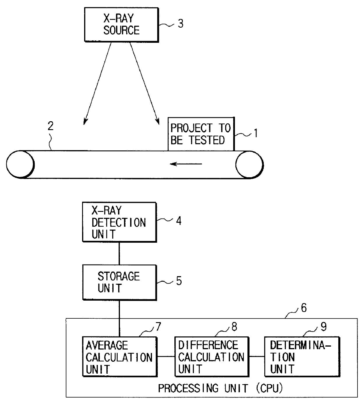
FIG. 1 shows the arrangement of the present invention.

As shown in FIG. 1, the contaminant-detecting apparatus of this embodiment is constituted by a belt 2 serving as a conveying means for conveying a product 1 to be tested, e.g., food, an X-ray source 3 for radiating X-rays to the product 1 to be tested, an X-ray detection unit 4 for detecting the X-rays transmitted through the product 1 to be tested, a storage unit 5 for storing the two-dimensional distribution of the X-ray intensity detected by the X-ray detection unit 4 as a transmission image, an average calculation unit 7 for performing a sum-of-product operation for a kernel equal to or larger than 7.times.7 pixels around each pixel of the transmission image by using a predetermined coefficient matrix to calculate the weighted average over the kernel, a difference calculation unit 8 for calculating the difference between the intensity of the given pixel and the weighted average over the kernel of this pixel, and a determinati...

second embodiment

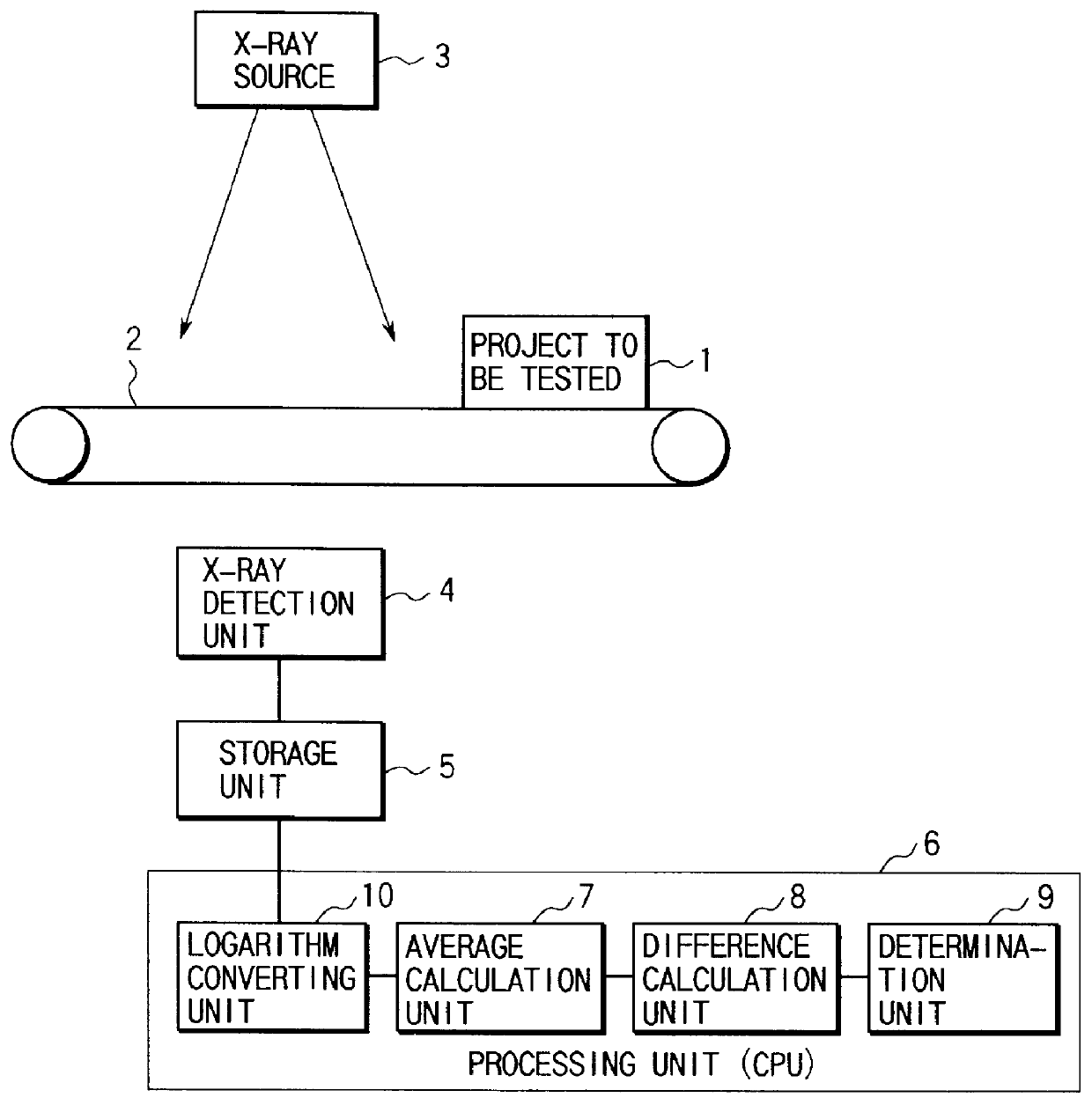
the present invention will be described with reference to FIG. 2.

The difference between the second and first embodiments is that in the second embodiment a logarithm converting unit 10 is added to a processing unit 6.

As shown in FIG. 2, when a product 1 to be tested is conveyed with a belt 2 serving as the conveying means and passes under an X-ray source 3, X-rays corresponding to the X-ray transmission coefficient of the product 1 to be tested are transmitted through the product 1 to be tested.

The X-rays which are transmitted through the product 1 to be tested are continuously detected by an X-ray detection unit 4.

The intensity of X-rays detected by the X-ray detection unit 4 is stored in a storage unit 5.

Hence, a transmission image as the two-dimensional distribution of the transmitted X-ray intensity is obtained.

According to this apparatus, the transmission image obtained in this manner is subjected to predetermined image processing with the processing unit 6 constituted by a log...

third embodiment

the present invention will be described.

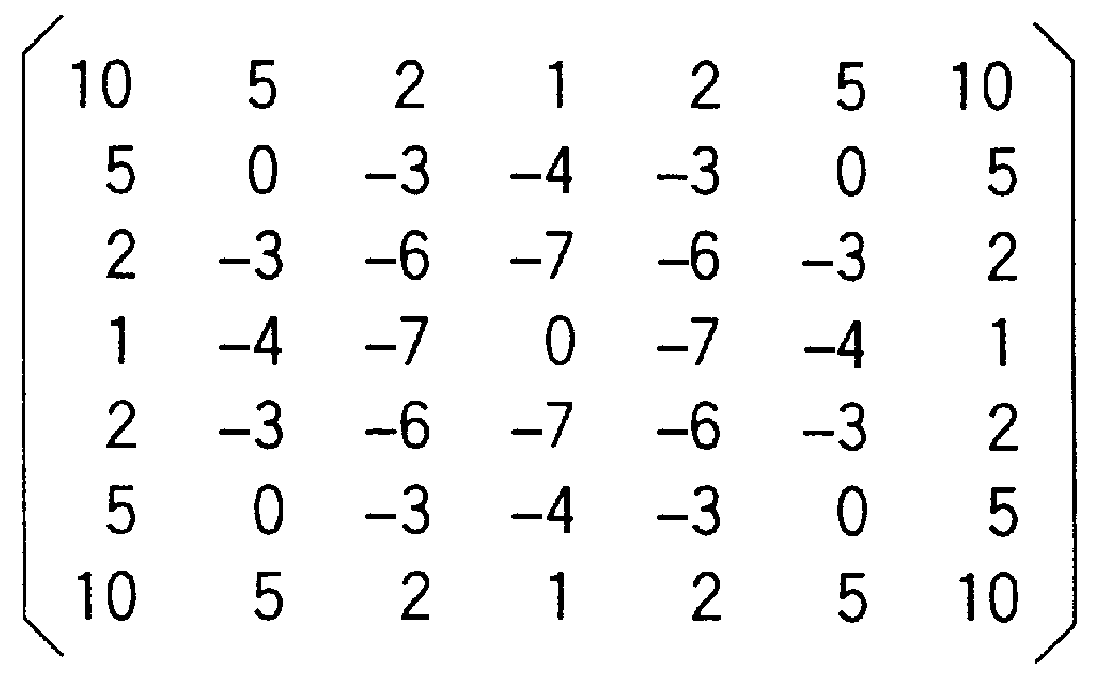
In the third embodiment, the arrangement of the apparatus is the same as that of the first or second embodiment, and is different from that of the first or second embodiment in the coefficient matrix which is used in an average calculation unit 7 that calculates the weighted average over the kernel.

As shown in FIG. 3, in the coefficient matrix of the average calculation unit 7 that calculates the weighted average over the kernel used in this embodiment, all of the 7.times.7=49 coefficients are 1.

More specifically, in the average calculation unit 7, the intensities of all the 49 pixels are multiplied by the coefficients 1 of the coefficient matrix. All the products are summed, and the sum is divided by 49, which is the sum of the coefficients.

When this coefficient matrix is used, the average calculation unit 7 calculates the weighted average over the kernel by using the intensities of all the pixels around the given pixel in the 7.times.7 pixel...


PUM


Abstract

PCT No. PCT/JP96/03778 Sec. 371 Date Apr. 17, 1998 Sec. 102(e) Date Apr. 17, 1998 PCT Filed Dec. 25, 1996 PCT Pub. No. WO98/11456 PCT Pub. Date Mar. 19, 1998This invention provides a contaminant-detecting apparatus having high selectivity and high sensitivity against a contaminant. A product (1) is conveyed to a point where it is irradiated by x-rays from source (3). An x-ray detector (4), having a predetermined detection unit width in a direction perpendicularly intersecting the conveying direction, then detects the x-rays transmitted through the product. A storage unit (5) stores a two-dimensional distribution of x-ray intensity detected by the x-ray detector as a transmission image in units of pixels. An average calculation unit (7) performs a sum-or-product operation of a kernel, which is equal to or larger than 7x7 pixels, (9x9 or 11x11), and equal to or smaller than (a pixel count corresponding to +E,fra 1/2+EE the predetermined x-ray detection unit width)x(pixel count corresponding to +E,fra 1/2+EE the predetermined x-ray detection unit width), and includes a target pixel, in units of pixels of the transmission image stored in the storage unit by using a predetermined coefficient matrix, thereby calculating the weighted average over the kernel. A difference calculation unit (8) calculates the difference between the x-ray intensity of the target pixel of the transmission image stored in the storage unit and the weighted average over the kernel of the target pixel which is calculated by the difference calculation unit. A determination unit (9) compares the difference calculated by the difference calculation unit with predetermined criteria, thereby determining presence/absence of a contaminant in the product to be tested.

Description

The present invention generally relates to a contaminant-detecting apparatus using X-rays and, more particularly, to a contaminant-detecting apparatus for radiating X-rays toward a product to be tested, e.g., food, conveyed by a conveying means, and processing an obtained X-ray transmission image, thereby detecting a small contaminant, e.g., metal, stone, glass, or the like, mixed in the product to be tested, in real time with high sensitivity.As is known, a contaminant-detecting apparatus for determining presence / absence of a contaminant mixed in a product to be tested by using an X-ray transmission image is constituted by a convey means for conveying the product to be tested, an X-ray source means for radiating X-rays toward the product to be tested, an X-ray detecting means for detecting the intensity of X-rays transmitted through the product to be tested, a storage means for storing a signal obtained with the X-ray detecting means as an X-ray transmission image, and a processing...

Claims


Application Information

Patent Timeline
IPC IPC(8): G01N23/04G01N23/02
CPCG01N23/04G01N23/046G01N2223/419
Inventor TAKAHASHI, YOSHIFUMISHIOIRI, KEN
Owner ANRITSU SANKI SYSTEM CO LTD
Why Eureka
Try Eureka