Method and system for controlling movement of a digging dipper

a technology of digging dipper and movement method, which is applied in the direction of program control, mechanical control devices, instruments, etc., can solve the problems of reduced return on investment, difficult task, and difficult to keep grade, so as to improve machine efficiency and minimize damage to crawler shoes.

Inactive Publication Date: 2000-02-15
HARNISCHFEGER TECH
View PDF43 Cites 113 Cited by
  • Summary
  • Abstract
  • Description
  • Claims
  • Application Information

AI Technical Summary

Benefits of technology

Yet another object of the invention is to provide a new method and system for controlling movement of a digging dipper which helps minimize damage to machine c...

Problems solved by technology

Given the configuration of known control apparatus, keeping grade is very difficult.
The task is made more difficult because lever movement in view of the desired dipper movement is not at all intuitive.
Time is wasted and given the fact that the shovel and the truck each cost well over a million dollars (in fact, a large mining shovel costs several million dollars), the return on the investment is diminished.
Another involves shoe and/or dipper damage.
The swing function rotates the machinery house with respect to the tracks and since a mining shovel is several stories high, it is difficult for the operator, seated far above ground le...

Method used


Image

  • Method and system for controlling movement of a digging dipper
  • Method and system for controlling movement of a digging dipper
  • Method and system for controlling movement of a digging dipper

Examples


Embodiment Construction

Overview

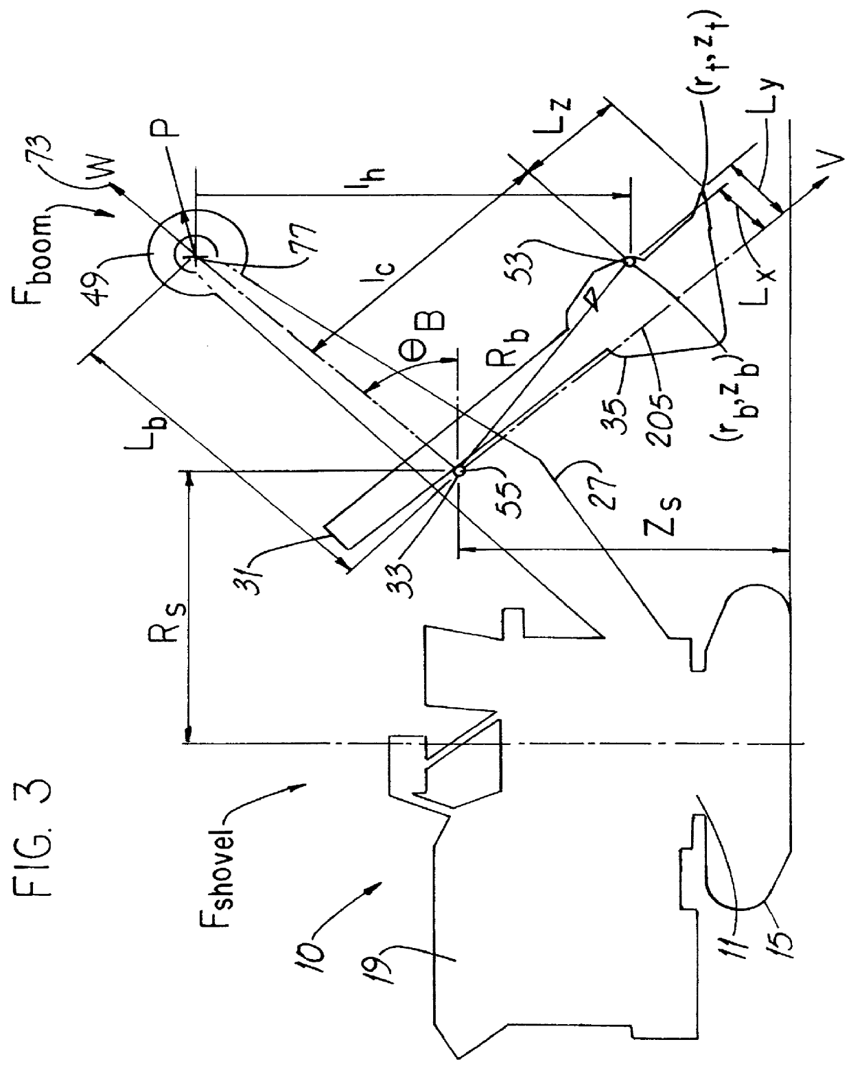
In this description and in the drawings, capital or upper case letters denote axes and fixed (i.e., constant) dimensions. Small or lower case letters denote variables.

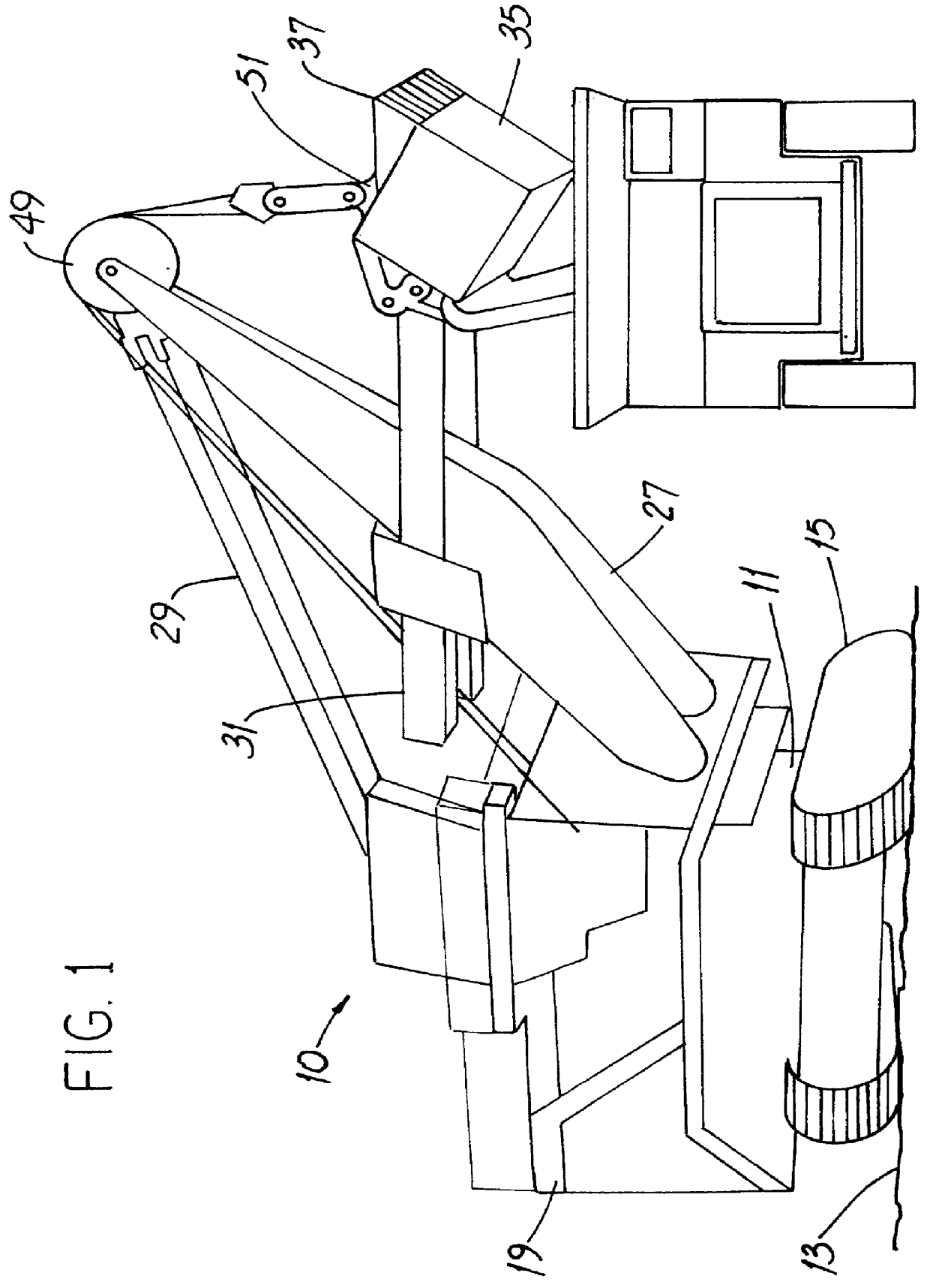
The following description uses an electrically-powered mining shovel as an example of a type of earthmoving machine with which the invention is used. However, it is to be understood (and those of ordinary skill will appreciate) that the invention is equally adaptable to hydraulic or hybrid machines.

The disclosed system uses what is known as closed loop or "feedback" control. Briefly described, feedback control involves generating a command signal which "tells" the system the path that the operator wants the dipper teeth to follow. Rotation of an electric motor, e.g., the hoist motor, is then "sensed" or "resolved" to provide a feedback signal "telling" the system the path the dipper teeth actually followed. The command and feedback signals are then compared and the "error" is used to automatically make incremen...


PUM


Abstract

A new method for controlling movement of a digging dipper includes providing an earthmoving machine with two drive systems for moving the dipper along two respective paths. Also provided is a control apparatus having a reference axis and a knob mounted for movement between a first, repose position and a maximum position spaced from the repose position by a maximum displacement dimension. The knob is displaced along a control axis to a second position which is spaced from the repose position by an actual displacement dimension less than the maximum displacement dimension. The drive systems are energized and the dipper is powered along a digging axis generally parallel to the control axis. A new apparatus for controlling movement of the dipper has a single control knob having a repose position and also has first and second motion transducers mechanically coupled to the knob. In a Cartesian coordinate system, the repose position is at the origin, the first transducer provides a first output signal when the knob is displaced along the "X" axis and the second transducer provides a second output signal when the knob is deflected from the repose position along the "Z" axis.

Description

This invention relates generally to earth working and, more particularly, to the control of electrically-powered earth working machines and / or "hybrid" earth working machines having both electrically and hydraulically powered systems used to position a digging dipper."Earth working" machines are made in a broad variety of machine type and drive system configurations. Two exemplary types of such machines in common use are mining shovels and draglines. Both are used in the process of extracting a valuable resource, e.g., coal, copper ore or the like, from the earth. Mining shovels, also referred to as excavators, and draglines can have a digging dipper or bucket capable of carrying anywhere from about 20 cubic yards (about 16 cubic meters) to about 120 cubic yards (about 100 cubic meters) or more of ore or the like. A leading manufacturer of mining shovels and draglines is Harnischfeger Corporation of Milwaukee, Wis.A typical earth working machine, e.g., a mining shovel, has a platfor...

Claims


Application Information

Patent Timeline
IPC IPC(8): E02F9/22E02F9/26E02F9/20E02F3/43E02F3/42
CPCE02F3/435E02F3/437E02F9/2004E02F9/2203E02F9/26E02F9/2025Y10T74/20201E02F9/2012
Inventor WICKERT, FRANCIS G.CHANG, SHU-CHIEHHALWAS, ANGELA R.LOKHORST, DAVID M.ROY, BRYAN D.
Owner HARNISCHFEGER TECH
Why Eureka
Try Eureka