Optical disk and method of manufacturing the same

Inactive Publication Date: 2000-02-15
KK TOSHIBA
View PDF4 Cites 17 Cited by
  • Summary
  • Abstract
  • Description
  • Claims
  • Application Information

AI Technical Summary

Benefits of technology

in structure. This is a practical advantage of the present invention.
A method of manufacturing an optical disk, according to the present invention, comprises: a first step of applying a exposure light beam modulated in accordance with an information signal to be recorded, thereby forming a pit train in a master; and a second step of manufacturing an optical disk by using the master, the optical disk having a readable mark train, in which information is recorded, by applying a light beam to the optical disk, wherein the first step includes a substep of increasing power of the exposure light beam corresponding to shortest ones of marks to a value greater than power of the exposure light beam which corresponds to other marks.
In the method, the first step includes a substep of decreasing a pulse width of the exposure light beam which corresponds to shortest mark to a value less than a pulse width of the exposure light beam which corresponds to the other mark. Also in this method, the first step includes a substep of decreasing a pulse width of the exposure light beam which corresponds to all marks to a value less than a pulse width of the information signal.
The method can provide an optical disk having a mark train, including the shortest marks which are arranged at a pitch shorter than the diameter of a reproducing beam spot and which have a width larger than those of the other marks.
The exposure light beam applied to form the shortes

Problems solved by technology

This inevitably reduces the amplitude of the signals reproduced from the optical disk.
Having an insufficient amplitude, the signal is likely to have increased

Method used


Image

  • Optical disk and method of manufacturing the same
  • Optical disk and method of manufacturing the same
  • Optical disk and method of manufacturing the same

Examples


Example

First Embodiment

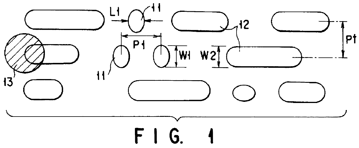
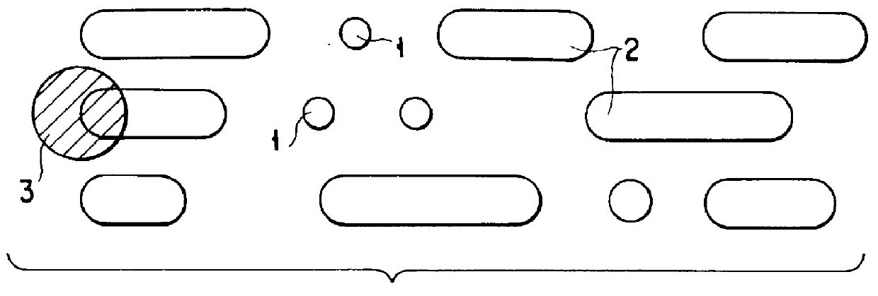
FIG. 1 shows some shapes of the pits formed in the surface of the optical disk. An optical disk of this type can reproduce the information and cannot write the information. The optical disk comprises a resin substrate and a reflecting film provided on the resin substrate. Information is recorded in the form of pits, on that surface of the disk on which the reflecting film is provided. The pits are arranged either in concentric tracks or in a spiral track. As seen from FIG. 1, the pits 11 and 12 have different lengths. Among the pits 11 are the shortest ones (shortest pit).

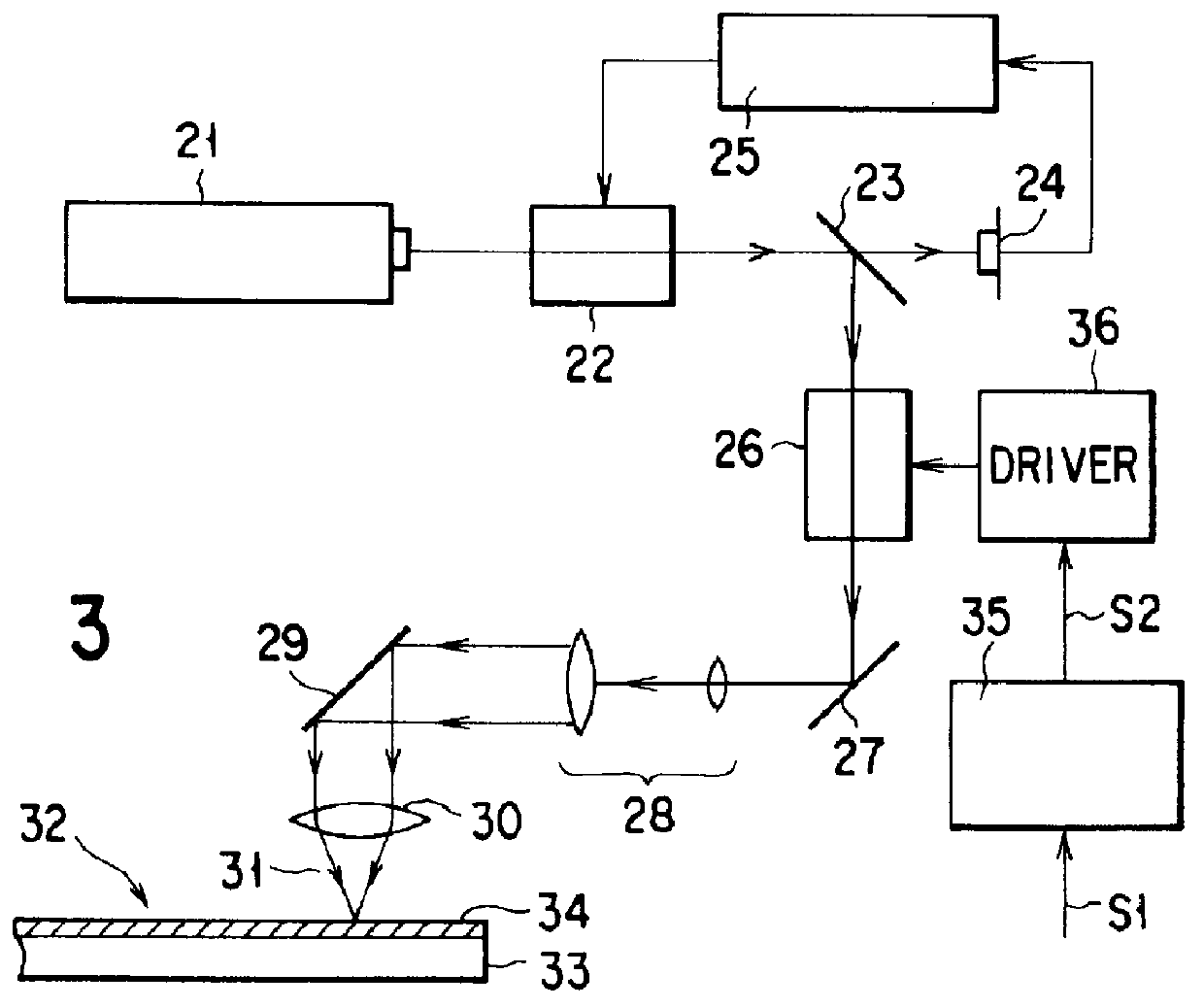
The information is reproduced from the optical disk by receiving light beams reflected from the pits 11 and 12 by an optical head (not shown). The optical head may be the known type which comprises a semiconductor laser element (i.e., a light source), a collimator lens, a beam splitter, an objective lens, a focusing lens, and a photodetector. The semiconductor laser element emits a laser beam. The l...

Example

Second Embodiment

The second embodiment of the present invention is also an optical disk. This optical disk is identical from the disk according to the first embodiment in that the pitch of the shortest pits 11 is shorter than the diameter of the reproducing beam spot and that the width of the shortest pits 11 is greater than the width of the other pits. The second embodiment is characterized in that the exposure laser beam 31 has a cross section elongated widthwise of the pits to be formed, that is, along the radius of the master 32. A recording laser beam having such an elongated cross section makes it easier to form pits of a desired shape.

FIG. 8 shows the exposure optical system which is incorporated in the apparatus for manufacturing the master 32 according to the second embodiment. The system is identical to the exposure optical system of FIG. 3, except that an elliptical aperture 51 is provided in the optical path to the objective lens 30, more precisely in front of the mirror...

Example

Third Embodiment

The third embodiment of this invention is an optical disk, too. This disk is of the same type as the optical disks according to the first and second embodiments. FIG. 9 shows the exposure optical system which is incorporated in the apparatus for manufacturing the master 32 according to the third embodiment. The system is characterized in that an super-resolution filter 61 is provided in the optical path to the objective lens 30, more correctly in front of the mirror 29. As shown in FIG. 9, the filter 61 has a stripe-shaped shield which extends in the radial direction of the master 32. FIG. 10 shows another type of an exposure optical system which may replace the system shown in FIG. 9 and which has an super-resolution filter 62 provided in front of the mirror 26. As shown in FIG. 10, the filter 62 has an elliptical shield whose major axis extends in the radial direction of the master 32. In both FIG. 9 and FIG. 10, the objective lens 30 and the laser beam 52 applied ...


PUM


Abstract

An optical disk comprises a mark train, which has at least one shortest mark and at least one other mark, recording readable information by applying a light beam, wherein the shortest mark of the mark train have a width larger than that of the other mark.

Description

BACKGROUND OF THE INVENTIONThe present invention relates to an optical disk having information stored in high density in the form of a mark train such as a pit train, and also a method of manufacturing the optical disk by using a master.An optical disk is a recording medium on which information has been recorded in the form of a mark train, such as a pit train. The information can be read by applying a light beam onto the recording surface of the optical disk. The optical disk attracts much attention because it can work as a memory for storing a great amount of information in high density. Actually it has been used as a memory in various data-processing systems such as personal computers, and also as a medium recording audio and video signals. Research and development are undergoing to provide an optical disk which can store more information in higher density.How optical disks are manufactured will be briefly described. First, the master is plated. Using the master thus plated, a st...

Claims


Application Information

Patent Timeline
IPC IPC(8): G11B7/013G11B7/26G11B7/0045G11B7/00
CPCG11B7/24085G11B7/261G11B7/0045
Inventor TAIRA, KOZONAKANO, TOSHIYUKIMATSUMARU, MASAAKI
Owner KK TOSHIBA
Why Eureka
Try Eureka