Crankpin phase indexing method and apparatus

Inactive Publication Date: 2000-02-22
KOMATSU NTC LTD
View PDF23 Cites 15 Cited by
  • Summary
  • Abstract
  • Description
  • Claims
  • Application Information

AI Technical Summary

Problems solved by technology

The conventional phase indexing apparatus, however, has the problem that the apparatus is complicated in structure and is large in overall size, because the planetary gear mechanism includes numerous gears.
Also, there is the problem that the manufacturing cost is high.
In addition, since the gears in the planetary gear mechanism clatter or chatter, loud noise is produced, deteriorating the crankpin machining environment.
Also, the machining accuracy is lowered due to wear of the gears, and maintenance such as lubrication of the gears is required.
Accordingly, consideration must be given to the space where the Schmidt coupling 201 is installed, and also, the vibration produced is transmitted to the entire Schmidt coupling, which adversely affects the machining operation.
In addition, after long use of the unit, its rotary driving system may become loose due to wear or the like, possibly making the spindles fail to rotate in perfect synchronism.
With this conve

Method used


Image

  • Crankpin phase indexing method and apparatus
  • Crankpin phase indexing method and apparatus
  • Crankpin phase indexing method and apparatus

Examples


Embodiment Construction

Embodiments of this invention will be hereinafter described in detail with reference to FIGS. 1 through 10.

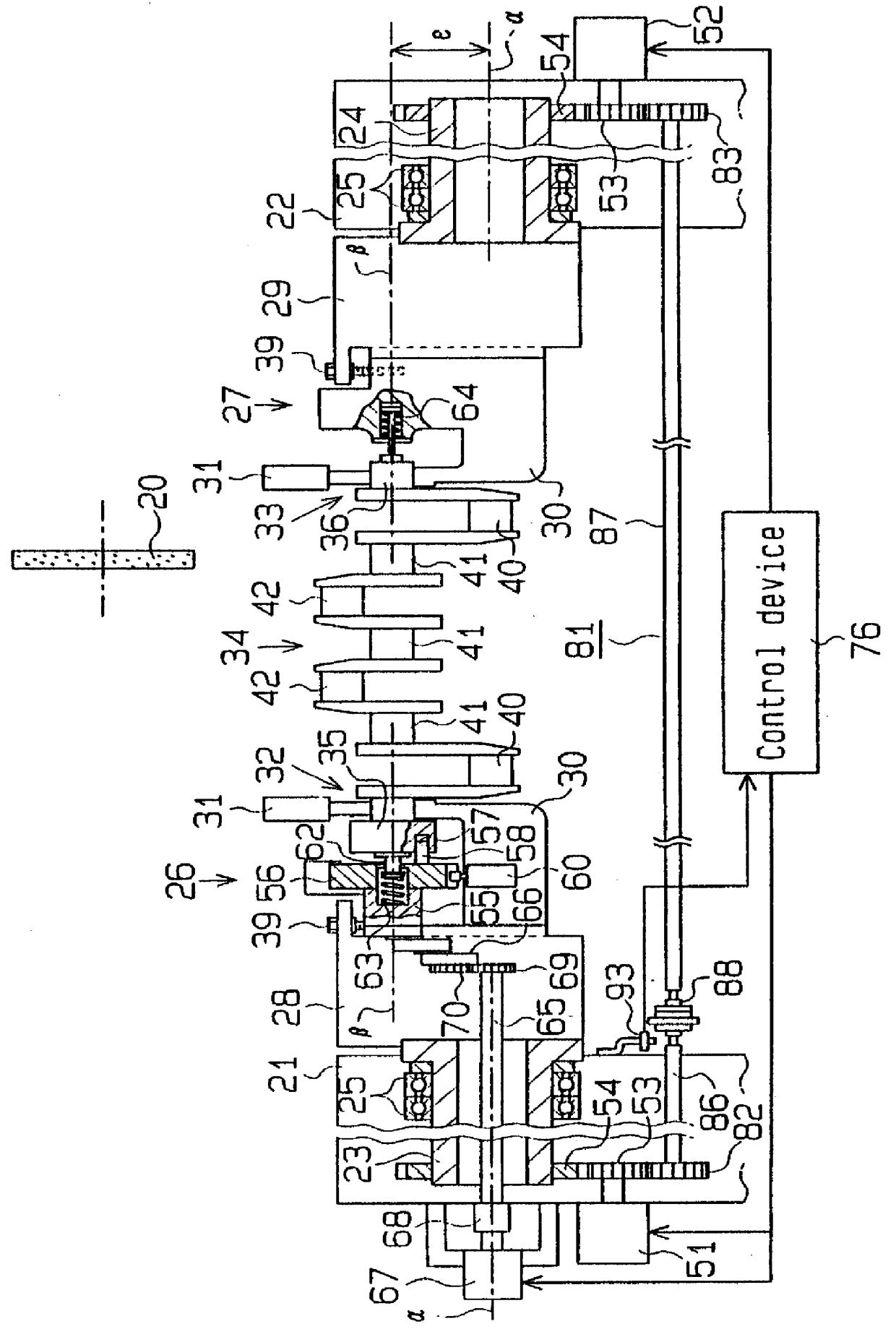
As shown in FIG. 1, a pair of head stocks 21 and 22 are placed on a table, not shown, so as to face each other with a predetermined distance therebetween. Hollow spindles 23 and 24 are rotatably supported by the respective head stocks 21 and 22 via bearings 25 such that they are in alignment with a first axis .alpha..

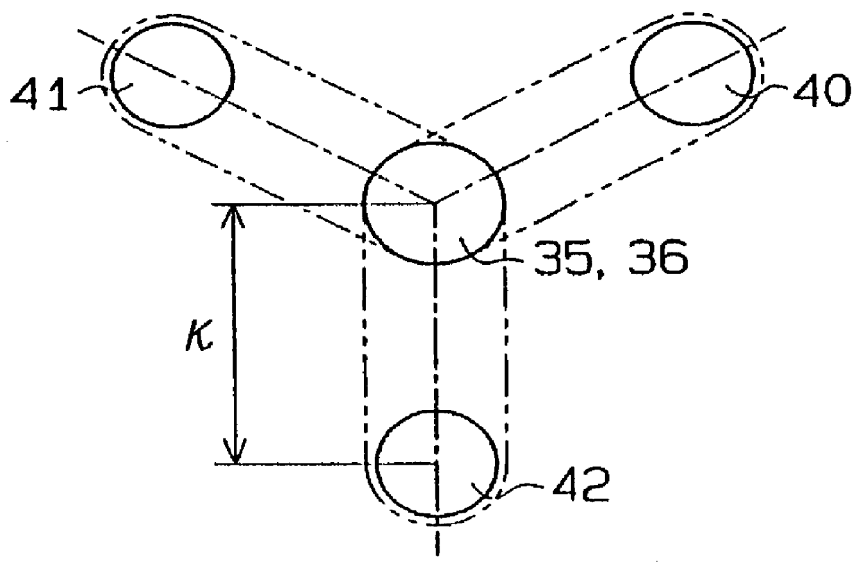
Chuck bodies 26 and 27 are mounted respectively to the inner ends of the spindles 23 and 24 through mounting members 28 and 29. Clamping sections 32 and 33, or chuck sections, each of which includes a holder 30 and a clamp arm 31, are arranged at the inner end portions of the chuck bodies 26 and 27, respectively. These clamping sections 32 and 33 serve to hold journals 35 and 36, which are on opposite ends of a crankshaft 34, respectively, in alignment with a second axis .beta. parallel to the first axis .alpha.. As shown in FIG. 2, the distance .epsilon. between t...


PUM

PropertyMeasurementUnit
Angleaaaaaaaaaa
Speedaaaaaaaaaa
Phaseaaaaaaaaaa

Abstract

PCT No. PCT/JP96/03292 Sec. 371 Date Jul. 25, 1997 Sec. 102(e) Date Jul. 25, 1997 PCT Filed Nov. 8, 1996 PCT Pub. No. WO97/19784 PCT Pub. Date Jun. 5, 1997A crankshaft phase indexing apparatus of this invention is provided with a pair of spindles arranged in alignment with a first axis. The Spindles are rotated respectively by a pair of spindle driving motors, which are controlled to rotate at the same speed. Chucks are mounted to the respective spindles. The chucks hold ends of a crankshaft in alignment with a second axis, which is displaced from and parallel to the first axis. A phase conversion shaft is rotatably arranged in at least one of the chucks in alignment with the second axis. The phase conversion shaft is connected to the crankshaft for rotating the crankshaft to permit phase indexing of crankpins of the crankshaft into axial alignment with the first axis. A phase indexing shaft, which is coupled to the phase conversion shaft, is located concentrically with the spindles and is rotated by a phase indexing motor. A control device for controlling the phase indexing motor and the spindle driving motors executes a first mode, in which the phase conversion shaft is revolved with the pair of spindles about the first axis to perform an operation on the crankshaft, and a second mode, in which the phase conversion shaft is rotated about the second second axis to index the crankshaft. Further, a link coupling is located between the phase conversion shaft and the phase indexing shaft. The link coupling is capable of changing the center distance between the first and second axes.

Description

1. Field of the InventionThis invention relates to a crankpin phase indexing apparatus and a phase indexing method applied to a crankpin grinding machine for machining, for example, grinding or polishing, a crankpin of a crankshaft.2. Description of the Related ArtIn this type of crankpin phase indexing apparatus, in general, two spindles are rotatably supported by a pair of head stocks, respectively, in axial alignment with each other, and chucks for holding journals on both ends of a crankshaft at locations spaced from the axis of the spindles are mounted to the inner ends of the respective spindles. Spindle driving motors are coupled to the pair of head stocks, respectively. As the spindles are rotated by the respective spindle driving motors, the crankshaft turns around its crankpin that is located in axial alignment with the spindles, whereby the outer peripheral surface of this crankpin can be subjected to machining such as grinding or polishing by means of a rotating grinding...

Claims


Application Information

Patent Timeline
IPC IPC(8): B23Q16/02B23Q16/00B23Q1/54B24B47/00B24B47/22B24B5/42B24B5/00B23Q1/25
CPCB23Q1/5468B23Q16/02B23Q16/025B24B5/42B24B47/22Y10T29/5109Y10T409/303752Y10T29/17Y10T29/49286Y10T409/305656Y10T409/30756Y10T82/19
Inventor MAKINO, KUNIOIMAI, TAKASHIUCHIDA, HIROYUKIKOKAJI, YUKIO
Owner KOMATSU NTC LTD
Why Eureka
Try Eureka