Cold cathode fluorescent lamp driving apparatus using a piezoelectric transformer

a technology of piezoelectric transformer and fluorescent lamp, which is applied in the direction of dc-ac conversion without reversal, process and machine control, instruments, etc., can solve the problems of limiting the realization of a smaller and thinner transformer, the development of the piezoelectric transformer was suspended,

Inactive Publication Date: 2000-02-22
PANASONIC PHOTO & LIGHTING CO LTD +1
View PDF4 Cites 14 Cited by
  • Summary
  • Abstract
  • Description
  • Claims
  • Application Information

AI Technical Summary

Problems solved by technology

However, material restrictions such as a breaking strength of a piezoelectric ceramic material prevented a piezoelectric transformer from being greatly commercially introduced, and its development was suspended.
In order to ensure a withstand voltage, however, there is a limit for realizing a smaller and thinner transformer.
In addition, because the core loss is large and the use of a thin copper wire causes the winding loss to be increased, the efficiency is disadvantageously low.
The self-excited oscillation circuit system has a problem in conversion efficiency, and contains drawbacks such as that the system cannot follow a large fluctuation of loads.
Thus, the cold cathode fluorescent lamp 105 cannot keep sufficient brightness.
In the case where the cold cathode fluorescent lamp is driven by an AC voltage of a high frequency, particularly, the changes are considerably large and complicated.
Thus, the prior art driving apparatuses cannot comply with the changes, and the current flowing through the cold cathode fluorescent lamp is pulsated so that brightness cannot be kept constant.
As a result, there exist problems in that the reliability of the cold cathode fluorescent lamp is reduced, and that the life period of the lamp is shortened.
In addition, the piezoelectric transformer is greatly disturbed by the pulsation so that heat generation is increased.
As a result, there exists a problem in that the reliability is significantly degraded.
Because of the connection of the resistor, even if the impedance of the cold cathode fluorescent lamp decreases, the piezoelectric transformer cannot supply a large current.
Even if the impedance of the cold cathode fluorescent lamp decreases, therefore, the piezoelectric transformer cannot supply a large current.

Method used


Image

  • Cold cathode fluorescent lamp driving apparatus using a piezoelectric transformer
  • Cold cathode fluorescent lamp driving apparatus using a piezoelectric transformer
  • Cold cathode fluorescent lamp driving apparatus using a piezoelectric transformer

Examples


embodiment 1

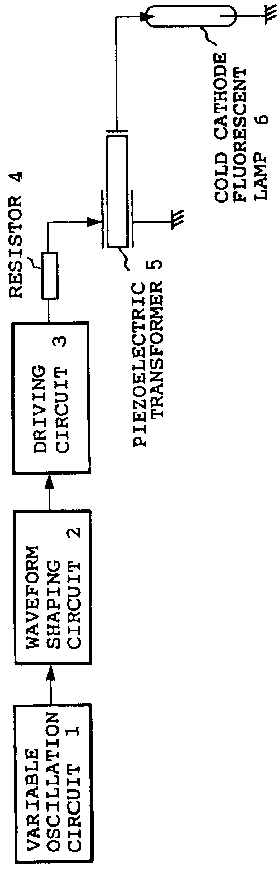
FIG. 1 is a block diagram showing a cold cathode fluorescent lamp driving apparatus using a piezoelectric transformer, i.e., an inverter circuit. In the figure, the piezoelectric transformer 5 may be a piezoelectric transformer of any desired type, i.e., a Rosen type or another type. A variable oscillation circuit 1 generates an AC driving signal of a frequency in the vicinity of the resonance frequency of the piezoelectric transformer 5. When the piezoelectric transformer 5 is driven by a driving signal having a rectangular waveform, components other than those in the vicinity of the resonance frequency are transformed into heat in the piezoelectric transformer 5. In the view point of the reliability of the piezoelectric transformer 5 and the conversion efficiency, the waveform of the output signal of the variable oscillation circuit 1 is shaped so as to be substantially sinusoidal by a waveform shaping circuit 2. In a simple case, the waveform shaping circuit 2 is a low pass filte...

embodiment 2

FIG. 5 is a block diagram showing a cold cathode fluorescent lamp driving apparatus using a piezoelectric transformer, i.e., an inverter circuit of Embodiment 2 of the invention. In the figure, a piezoelectric transformer 5 may be a piezoelectric transformer of any desired type, i.e., a Rosen type or another type. A variable oscillation circuit 1 performs a frequency regulation so as to generate an AC driving signal of a frequency in the vicinity of the resonance frequency of the piezoelectric transformer 5. When the piezoelectric transformer 5 is driven by a driving signal having a pulse waveform, components other than those in the vicinity of the resonance frequency are transformed into heat in the piezoelectric transformer 5 without contributing to the voltage transformation. In the view point of the reliability of the piezoelectric transformer 5 and the conversion efficiency, the waveform of the output signal of the variable oscillation circuit 1 is shaped so as to be substantia...

embodiment 3

FIG. 8 is a block diagram showing a cold cathode fluorescent lamp driving apparatus using a piezoelectric transformer, i.e., an inverter circuit as an example of Embodiment 3 of the invention. In the figure, the piezoelectric transformer 5 may be a piezoelectric transformer of any desired type, i.e., a Rosen type or another type. A variable oscillation circuit 1 generates an AC driving signal of a frequency in the vicinity of the resonance frequency of the piezoelectric transformer 5. When the piezoelectric transformer 5 is driven by a driving signal having a rectangular waveform, components other than components in the vicinity of the resonance frequency are transformed into heat in the piezoelectric transformer 5. In the view point of the reliability of the piezoelectric transformer 5 and the conversion efficiency, the waveform of the output signal of the variable oscillation circuit 1 is shaped so as to be substantially sinusoidal by a waveform shaping circuit 2. In a simple case...


PUM


Abstract

An AC driving signal of a frequency in the vicinity of the resonance frequency of a piezoelectric transformer is generated by a variable oscillation circuit and the waveform of the output signal of the variable oscillation circuit is shaped so as to be substantially sinusoidal by a waveform shaping circuit and the output of the waveform shaping circuit is subjected by a driving circuit to current amplification or voltage amplification so as to be amplified to a level sufficient for driving the piezoelectric transformer and the output of the driving circuit is subjected to current limitation, and then input to the piezoelectric transformer and the output signal of the transformer is applied to a cold cathode fluorescent lamp so that the cold cathode fluorescent lamp is lit and even if the impedance of the cold cathode fluorescent lamp decreases, the piezoelectric transformer cannot supply a large current.

Description

1. Field of the InventionThe invention relates a cold cathode fluorescent lamp driving apparatus using a piezoelectric transformer which transforms the amplitude of an AC voltage by the piezoelectric effect of a piezoelectric element such as a piezoelectric ceramics.2. Related Art of the InventionA piezoelectric transformer developed at the end of the nineteen fifties was further developed because it received attention as a step-up transformer for a high voltage power source. However, material restrictions such as a breaking strength of a piezoelectric ceramic material prevented a piezoelectric transformer from being greatly commercially introduced, and its development was suspended. In recent years, development of a high-strength piezoelectric ceramic progresses, and portable information devices such as note-type personal computers, electronic organizers, and game machines are significantly required to be smaller and thinner. With such development and requirements, great attention ...

Claims


Application Information

Patent Timeline
Patent Type & Authority Patents(United States)
IPC IPC(8): H05B41/28H05B41/282H01L41/107H05B41/24H02M7/48H05B41/02H05B41/232
CPCH05B41/2822Y10S315/07Y10S315/05H05B41/14
Inventor KAWASAKI, OSAMUIWATA, HIROSHIMURATA, KAZUOUMAKINO, HIROSHIHASEGAWA, WATARU
Owner PANASONIC PHOTO & LIGHTING CO LTD
Why Eureka
Try Eureka