DC-to-DC converter capable of preventing overvoltage

a dc-to-dc converter and converter technology, applied in the direction of electric variable regulation, process and machine control, instruments, etc., can solve the problems of deteriorating dc/dc converter conversion efficiency, fire and smoke explosion, and easy destruction of organic capacitors

Inactive Publication Date: 2000-02-22
FUJITSU LTD
View PDF28 Cites 81 Cited by
  • Summary
  • Abstract
  • Description
  • Claims
  • Application Information

AI Technical Summary

Problems solved by technology

When the resistance value of this equivalent series resistor (ESR) is large, the converting efficiency of the DC/DC converter would be deteriorated.
On the other hand, as explained above, although organic capacitors own great merits such as high frequency characteristics and temperature characteristics, these organic capacitors have such demerits that the organic capacitors are easily destroyed by receiving overvoltages, resulting in fire and smoke explosion.
That is, the output voltage is increased due to circuit failure of this DC/DC converter.
Also, since the cells and the recharging devices malfunction, or improper cells/recharging devices are employed, the voltage inputted into the DC/DC converter is increased to produce the overvoltage.
To the contrary, when this zener diode fails in the opencircuit mode, the organic capacitor provided in the output unit of the DC/DC converter would be burned out, resulting in fire and smoke explosion.
Furthermore, it is practically impossible to define whether the zener diode fails in the opencircuit mode, or the shortcircuit mode.
As a consequence, it is improper to utilize such a zener diode as the protection circuit of the DC/DC converter.
In addition, there is another problem that sin

Method used


Image

  • DC-to-DC converter capable of preventing overvoltage
  • DC-to-DC converter capable of preventing overvoltage
  • DC-to-DC converter capable of preventing overvoltage

Examples


first embodiment

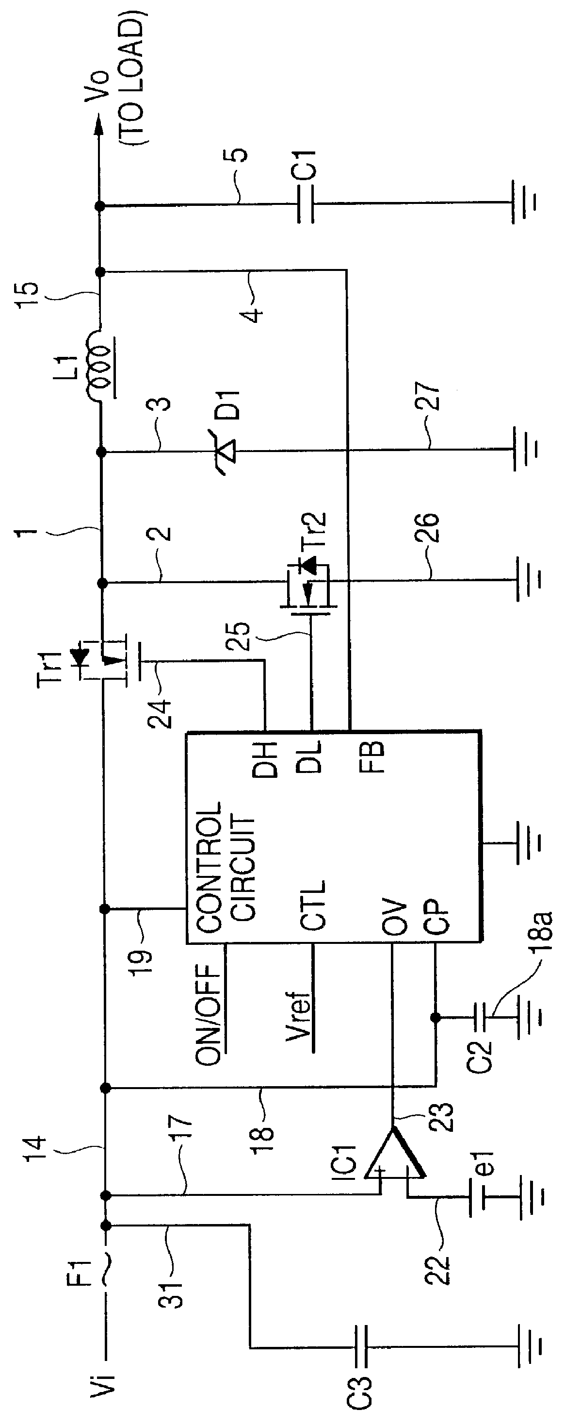
FIG. 1 is a schematic diagram for showing a DC-to-DC converter mode 1 of the present invention. It should be noted that the same reference numerals used in the prior art DC / DC converter will be employed as those for denoting the same or similar constructive elements in the following embodiment modes.

A DC / DC converter is provided between a cell functioning as a power supply and a load (not shown in FIG. 1), and is such an apparatus for converting a voltage applied from the cell into a constant voltage so as to supply this constant voltage to the load.

(ARRANGEMENT OF FIRST DC / DC CONVERTER)

The DC / DC converter according to this embodiment mode 1 is constructed of a fuse F1, a control circuit CTL, a main switching transistor Tr1, a synchronous rectification transistor Tr2, a diode D1, a choke coil L1, a capacitor C1, a voltage comparator IC1, a power supply e1 for producing a reference voltage e1, a capacitor C2, and a capacitor C3.

(CIRCUIT CONNECTIONS FOR FIRST DC / DC CONVERTER)

Now, con...

embodiment mode 2

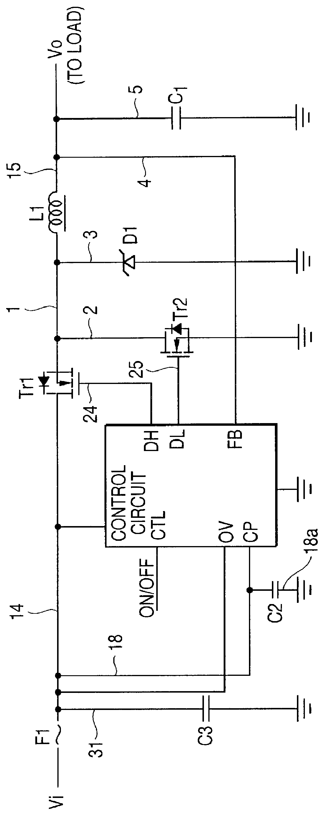
FIG. 2 is a schematic diagram for showing a DC-to-DC converter according to a second embodiment mode 2 of the present invention. It should be noted that the same reference numerals used in the first DC / DC converter will be employed as those for denoting the same or similar constructive elements in the following embodiment modes.

A DC / DC converter is provided between a cell functioning as a power supply and a load.

(ARRANGEMENT OF SECOND DC / DC CONVERTER)

The DC / DC converter according to this embodiment mode 2 is constructed of, a control circuit CTL, a main switching transistor Tr1, a synchronous rectification transistor Tr2, a diode D1, a choke coil L1, a capacitor C1, a voltage comparator IC2, and a power supply e3 for producing a reference voltage e3.

(CIRCUIT CONNECTIONS FOR SECOND DC / DC CONVERTER)

Now, connection modes of the above-described constructive elements will be described.

The main switching transistor Tr1 is connected via a signal line 14 to a call. This main switching trans...

embodiment mode 3

FIG. 9 is a schematic diagram for showing a DC-to-DC converter according to a third embodiment mode 3 of the present invention. It should be noted that the same reference numerals used in the above-described embodiment modes 1 and 2 will be employed as those for denoting the same or similar constructive elements in the following embodiment mode.

(ARRANGEMENT OF THIRD DC / DC CONVERTER)

The DC / DC converter is constructed of a fuse F1, a voltage comparator IC1, power supply e1, capacitor C3, capacitor C2, an OR gate circuit OR3, a control circuit CTL, a main switching transistor Tr1, a synchronous rectification transistor Tr2, a diode D1, a choke coil L1, a resistor R1a, capacitor C1, a voltage comparator IC2, and a power supply e3.

(CIRCUIT CONNECTIONS FOR THIRD DC / DC CONVERTER)

Now, connection modes of the above-described constructive elements will be described.

The fuse F1 is employed in a half way of a signal line 14 used to connect the cell with the main switching transistor Tr1.

The mai...


PUM


Abstract

To avoid burning out a capacitor in a synchronous rectification type DC-to-DC converter due to overvoltages, the synchronous rectification type DC-to-DC converter includes a storage unit storing therein power derived from a power supply, switching elements connecting and disconnecting respective signal paths from power and ground, and a control unit controlling the connecting/disconnecting operations of the switching elements to maintain a voltage output from the storage unit at a predetermined value. The DC/DC converter also includes an overvoltage detecting unit monitoring a voltage derived from the power supply to thereby output an alarm signal when the voltage derived from the power supply exceeds a preselected voltage value, a shortcircuiting unit influencing the connecting conditions of the switching elements when the alarm signal from the overvoltage detecting unit is input therein, whereby the voltage derived from the power supply is shortcircuited, and an interrupting unit interrupting one of the signal paths by the power shortcircuited by the shortcircuiting unit.

Description

1). Field of the InventionThe present invention generally relates to a DC-to-DC converter. More specifically, the present invention is directed to a voltage drop type DC-to-DC converter capable of preventing overvoltages appearing in an input voltage and an output voltage.2). Description of the Prior ArtPortable type electronic appliances such as notebook type personal computers install cells as power supplies thereof. To operate these portable type electronic appliances under stable conditions, these cells are preferably capable of supplying constant voltages.To the contrary, general-purpose cells inherently owns such a characteristic that output voltages are gradually lowered during discharge operation. Therefore, portable type electronic appliances are equipped with DC-to-DC converters capable of maintaining the output voltages of these cells at constant values.The operation time during which an electronic appliance can be effectively operated by a cell is one of the major import...

Claims


Application Information

Patent Timeline
IPC IPC(8): H02H7/12H02M3/04H02M3/158H02H7/16H02H7/00
CPCH02H7/1213H02M3/1588H02H7/16Y02B70/1466Y02B70/10
Inventor SAEKI, MITSUOYANO, HIDETOSHIOZAWA, HIDEKIYO
Owner FUJITSU LTD
Why Eureka
Try Eureka