Method of drop size modulation with extended transition time waveform

a transition time waveform and drop size technology, applied in the direction of liquid spraying apparatus, printing apparatus, printing, etc., can solve the problems of limiting the throughput of a printhead system, limiting the usefulness of such technology in the printing arts, and failure to operate solder jet devices with orifice diameters greater than 75 .mu.m to make larger drops

Inactive Publication Date: 2000-02-29
MICROFAB TECH
View PDF15 Cites 95 Cited by
  • Summary
  • Abstract
  • Description
  • Claims
  • Application Information

AI Technical Summary

Problems solved by technology

Attempts to operate solder jet devices with orifice diameters greater than 75 .mu.m to make larger drops have been unsuccessful due to instability of the drop formation process.
Thus, multidroplet dispensing to a site inherently limits the throughput of a printhead system.
Without droplet placement accuracy, it is said the usefulness of such technology in the printing arts is minimal.
There is no incentive for conventional ink-jet technology to increase the length of waveform in an ink-jet for printing because it could decrease the operating frequency of the device.

Method used


Image

  • Method of drop size modulation with extended transition time waveform
  • Method of drop size modulation with extended transition time waveform
  • Method of drop size modulation with extended transition time waveform

Examples


Embodiment Construction

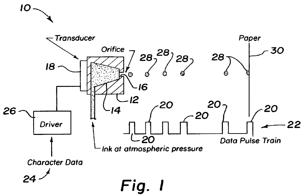
A drop-on-demand ink-jet printing system is schematically illustrated in FIG. 1. These are commonly known as demand mode ink-jet printing systems because they produce a microdroplet in response to a pulsed waveform as opposed to a continuous stream which is broken into droplets in a continuous mode system. In FIG. 1 demand mode system 10 is illustrated as having a printhead 12 containing an ink reservoir 14 with an ink supply and an outlet orifice 16. A transducer 18 is most commonly a piezoelectric material which is directly or indirectly coupled with the fluid in reservoir 14. A volumetric change in the fluid is induced by application of a voltage pulse 20 which may be part of a data pulse train generally indicated by the reference numeral 22. Character data 24 is delivered through an electronic control system comprising driver 26 which delivers a series of individual voltage pulses 20 through transducer 18. This volumetric change causes pressure / velocity transients to occur in th...


PUM


Abstract

The present invention uses a novel waveform to allow the droplet volume dispensed from a demand mode inkjet type device to be increased and selected according to easily controllable parameters. The current invention departs from the conventional drive method by significantly increasing the time for energy input in the initial instance as well is in all later application of the drive voltage to the device. In shape, the waveform is the same whether a unipolar or bipolar pulse is utilized; however, the transition times in the initial instance are up to three times the acoustic resonance and the delay times are of the same order. Droplet diameter can be varied from 1X the orifice diameter to 2X the orifice diameter resulting in an 8:1 range of droplet volume. Since the volume modulation results from changes in the waveform used to drive the solder jet device, the drop volume can be changed and altered in real time.

Description

1. Field of the InventionThe invention relates to increasing the size of microdrops produced by ink-jet technology to a size which is significantly larger than the orifice diameter; especially solder microdrops for use in the electronic industry.2. Background of the ArtAlthough this invention is applicable to the dispensing of various liquids, it has been found particularly useful in the environment of dispensing very small solder balls to very small soldering areas. Therefore, without limiting the applicability of the invention to "dispensing very small solder balls to very small soldering areas," the invention will be described with reference to that environment.In a high density electronic manufacturing process, semiconductor integrated circuit chips are bonded to a substrate by a solder reflow process. This is commonly referred to as a "flip-chip" process in which solder bumps are placed on pads of the integrated circuit chip or other chip, then turned over and matched with sold...

Claims


Application Information

Patent Timeline
Patent Type & Authority Patents(United States)
IPC IPC(8): B05B17/04B05B17/06B41J2/045
CPCB05B17/0607B41J2/04581B41J2/04588B41J2/04593
Inventor SELF, ROGER G.WALLACE, DAVID B.
Owner MICROFAB TECH
Why Eureka
Try Eureka