Thermal treatment apparatus with thermal protection members intercepting thermal radiation at or above a predetermined angle

a technology of thermal radiation treatment and thermal protection members, which is applied in lighting and heating apparatus, muffle furnaces, furnaces, etc., can solve the problems of difficult to sufficiently reduce the temperature difference between the central and peripheral edge portions of each wafer, easy to occur dramatic differences in temperature response characteristics, and slipping (crystal distortion) in the wafer, etc., to achieve rapid temperature rise or lowering, reduce the difference in temperature within the surface, and increase throughput

Inactive Publication Date: 2000-02-29
TOKYO ELECTRON LTD
View PDF6 Cites 25 Cited by
  • Summary
  • Abstract
  • Description
  • Claims
  • Application Information

AI Technical Summary

Benefits of technology

In general, a factor called the radiation view factor increases as the angle of incidence of thermal radiation from the heater increases (in other words, as the surface to be processed of the substrate becomes perpendicular to the incident rays), so that the peripheral edge portion of a substrate to be processed (such as a wafer) is more readily affected by thermal radiation. However, the provision of thermal protection members around the substrate to be processed in accordance with the present invention ensures the interception of thermal radiation from the heater that is incident at a predetermined angle of incidence or greater on the peripheral edge portions of the substrates to be processed, so that the effects due to thermal radiation on that peripheral edge portions can be actively controlled. Therefore, the effects of thermal radiation on the peripheral edge portions of the substrates to be processed are controlled in the thermal treatment apparatus of this invention, not only from the viewpoint of heat conduction through gases but also from heat transfer by radiation, unlike in the thermal treatment apparatus of the prior art, thus making it possible to reduce the difference in temperature within the surface between the central portion and peripheral edge portion of each wafer, not only under normal pressure within a thermal treatment chamber but also under reduced pressures. As a result, the temperature can be raised or lowered rapidly, enabling an increase in throughput.

Problems solved by technology

A dramatic difference can easily occur in the temperature response characteristics of the central portions and peripheral edge portions of the wafers, particularly if the temperature increases or decreases rapidly, and this tends to cause slipping (crystal distortion) in the wafers, due to internal stresses generated by temperature differences within the surfaces of the wafers.
For that reason, if the temperature within the reaction tube is raised or lowered rapidly in a reduced-pressure state, the effects of the ring-shaped support plates are not fully realized and it becomes difficult to sufficiently reduce the temperature difference between the central and peripheral edge portions of each wafer.
Therefore, since it is difficult to raise or lower the temperature rapidly under a reduced pressure in this prior-art thermal treatment apparatus, there is a limit to improvements in throughput.

Method used


Image

  • Thermal treatment apparatus with thermal protection members intercepting thermal radiation at or above a predetermined angle
  • Thermal treatment apparatus with thermal protection members intercepting thermal radiation at or above a predetermined angle
  • Thermal treatment apparatus with thermal protection members intercepting thermal radiation at or above a predetermined angle

Examples


embodiment 1

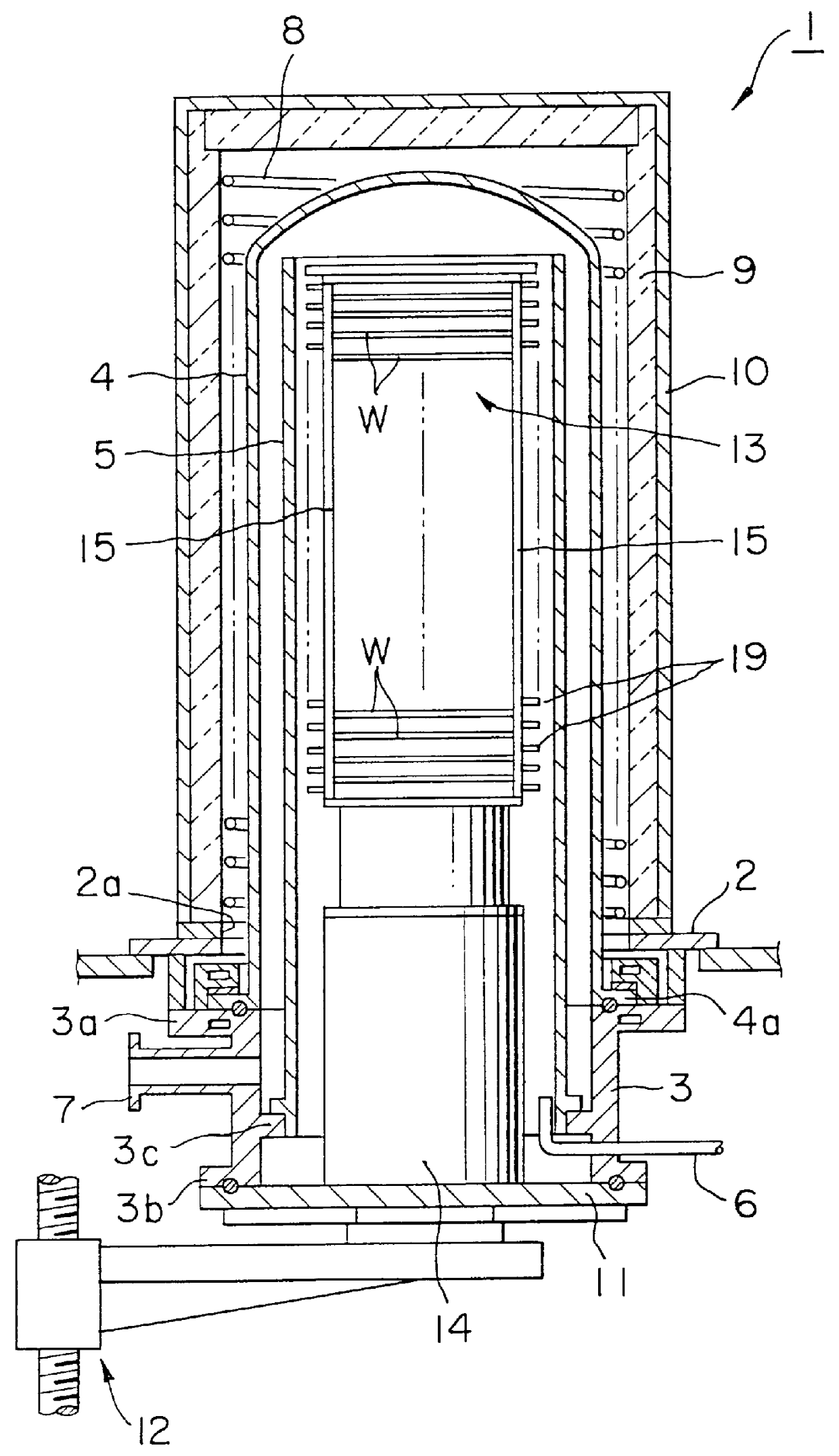
A first embodiment of a thermal treatment apparatus in accordance with this invention, when applied to a vertical thermal treatment apparatus, will be described below with reference to the accompanying drawings. In FIG. 1, reference number 1 denotes a vertical thermal treatment apparatus that is configured to perform a film-formation process by reduced-pressure CVD on a substrate to be processed, such as a semiconductor wafer W. A base plate 2 made of a material such as stainless steel and having a circular aperture portion 2a at the center thereof is provided horizontally. A short cylindrical manifold 3 made of a material such as stainless steel and having radially outwardly extending upper and lower flanges 3a and 3b is disposed below the base plate 2, concentric with the circular aperture portion 2a. A reaction tube 4 is a thermal treatment vessel made of a material that is heat resistant and corrosion resistant, such as non-transparent quartz, in the form of a vertical thermal t...

first embodiment

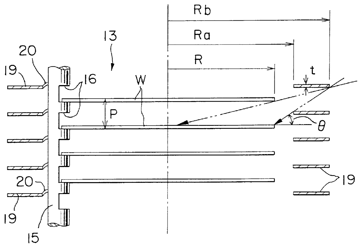
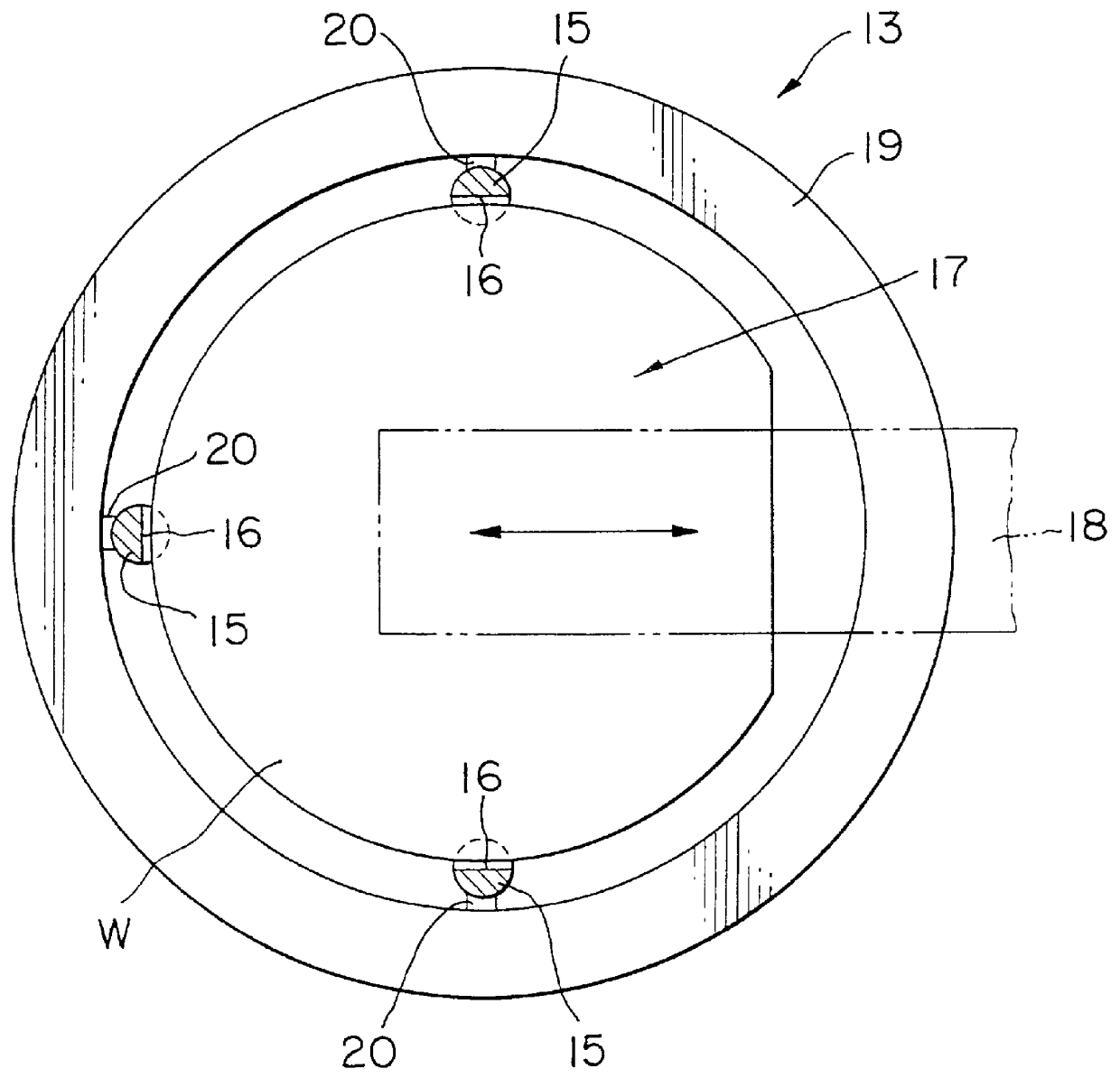
This first embodiment of the thermal treatment apparatus of this invention is particularly characterized in having annular insulating members (buffers) 19, which intercept thermal radiation from the heater that is incident on the peripheral edge portions of the wafers W at a predetermined angle of incidence .theta. or greater, disposed on the support pillars 15 of the wafer boat 13 so as to be positioned around the wafers W at the same spacing (pitch) as that of the wafers W, in a multi-level Venetian-blind form with each individual wafer W being positioned between thermal protection members 19 that are vertically adjacent, as shown in FIGS. 2 and 3. The thermal protection members 19 have heat-resisting and heat-insulating properties and are made of a material that is not likely to form a source of contamination of the wafers, such as non-transparent quartz. Furthermore, the thermal protection members 19 are formed to a flat annular shape of a size such that they fit loosely on the ...

embodiment 2

A second embodiment of the thermal treatment apparatus of this invention is shown in FIGS. 5 and 6. Components that are the same as those of Embodiment 1 are given the same reference numbers and further description thereof is omitted. As shown in these figures, a wafer boat 13 of this second embodiment has a plurality of support pillars 15 (three or four), such as three, disposed at a suitable spacing around the periphery of flat, annular thermal protection members 19. The annular thermal protection members 19 are fixed to the inner sides of these support pillars 15 in multiple stages at a suitable spacing in the vertical direction by welding or the like on outer edge portions thereof. Support portions 21 for supporting the wafers W between adjoining thermal protection members 19 are provided at a suitable spacing in the peripheral direction (at, for example, three equidistant locations) on upper surfaces of the inner edge portions of the thermal protection members 19 disposed in mu...


PUM

PropertyMeasurementUnit
temperatureaaaaaaaaaa
thicknessaaaaaaaaaa
outer radiusaaaaaaaaaa

Abstract

PCT No. PCT/JP96/00503 Sec. 371 Date Sep. 10, 1997 Sec. 102(e) Date Sep. 10, 1997 PCT Filed Mar. 1, 1996 PCT Pub. No. WO96/28843 PCT Pub. Date Sep. 19, 1996In a thermal treatment apparatus that accommodates substrates to be processed (W) in multiple stages within a reaction tube (4) and subjects them to a thermal treatment, thermal protection members (19) are provided around the peripheries of the substrates (W) to be processed to intercept thermal radiation that is incident on the peripheral edge portions thereof at a predetermined angle of incidence or greater. The peripheral edge portions of substrates (W) to be processed are generally more readily affected by thermal radiation as the angle of incidence of thermal radiation thereon increases, but, since thermal radiation from the heater at a predetermined angle of incidence ( theta ) or greater is intercepted by the thus disposed thermal protection members (19), the effects on thermal radiation on the peripheral edge portions of the substrates (W) to be processed are controlled. As a result, the temperature difference within the surface between the central portion and peripheral edge portion of each substrate to be processed (W) can be sufficiently reduced, not only under normal pressure within the reaction tube (4) but also under reduced pressures, and thus the temperature can be raised or lowered rapidly, enabling an increase in throughput.

Description

The present invention relates to a thermal treatment apparatus for substrates to be processed, such as semiconductor wafers.Various types of thermal treatment apparatus are used in the fabrication of semiconductor devices, to perform processes such as oxidation, diffusion, chemical vapor deposition (CVD), or annealing on a semiconductor wafer that is the substrate to be processed. One of these is a vertical thermal treatment apparatus which is capable of batch-processing a large number of wafers simultaneously and which is provided with a reaction tube (process tube) that functions as a thermal treatment chamber within a type of furnace called a hot-wall furnace, which has a heater disposed around the periphery thereof. A large number of substrates to be processed are held horizontally and in multiple stages at a suitable spacing in the vertical direction by a wafer boat that is means for supporting substrates to be processed within the reaction tube, and this large number of wafers...

Claims


Application Information

Patent Timeline
Patent Type & Authority Patents(United States)
IPC IPC(8): C30B31/00C30B31/12H01L21/00H01L21/22H01L21/205H01L21/324
CPCC30B31/12H01L21/67109H01L21/67115H01L21/22
Inventor SHIMAZU, TOMOHISA
Owner TOKYO ELECTRON LTD
Why Eureka
Try Eureka